PLC SCAN CYCLE
PLC Scan Cycle Explained: Inputs, Logic and Outputs
How a PLC reads inputs, runs its logic and writes outputs in a loop, with the Siemens, Rockwell and CODESYS details: the process image, watchdogs, response time, a worked timing example, and how to measure and cut scan time.

The PLC scan cycle is the loop a PLC repeats for as long as it is in RUN: it copies the state of every input into memory, executes the program from top to bottom using that copy, writes the results to the outputs, and handles communication and self-checks before starting again. The time one pass takes is the scan time, which Siemens calls the cycle time. Because inputs are read once per pass, a PLC reacts to a change within one to two scans, and it can miss a pulse shorter than one scan.
Checked on 11 October 2026 against the Siemens, Rockwell Automation and CODESYS documents listed under this post.
Every PLC language runs inside this loop, so the scan explains behaviour that otherwise looks like a bug: a rung that "ignores" a button, or a controller that faults when a loop runs too long. If you are new to PLCs, start with our complete guide to PLC programming.
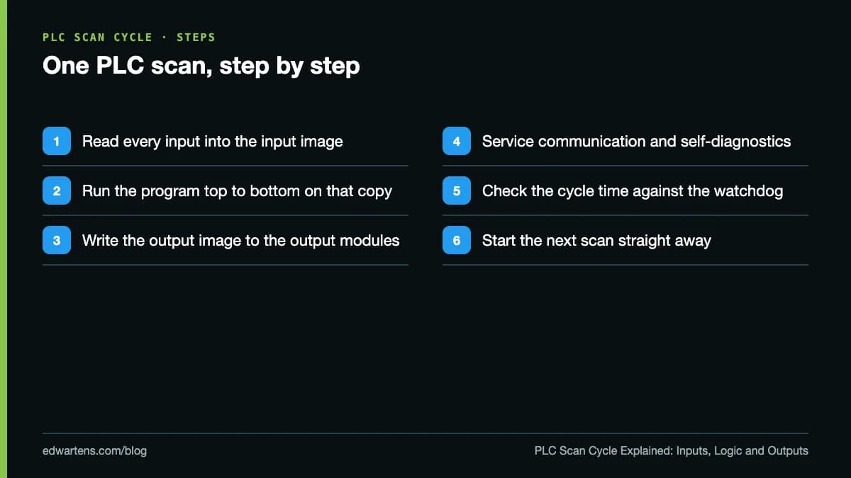
What are the steps of a PLC scan cycle?
Siemens' S7-1200 system manual describes each scan as writing the outputs, reading the inputs, executing the user program and performing background processing. Starting from the input read, a classic cyclic PLC does this:
- Read the inputs into the process image of the inputs.
- Execute the program from the first instruction to the last, reading the input image and writing results into the process image of the outputs, not to the terminals.
- Write the outputs: the output image is copied to the output modules.
- Communicate and run diagnostics. Siemens notes that communication is handled periodically throughout the scan and can interrupt the user program.
- Check the time and repeat. The cycle time is compared with the watchdog limit and the next scan starts at once, or waits if a minimum cycle time is set.
In this video, Instrumentation Tools explains the PLC scan cycle as part of its complete PLC and automation course. It is one of the lessons in our free Siemens TIA Portal in Three Hours course, and at under ten minutes it is a quick way to see the loop drawn out before the vendor detail below.
What is the process image?
The process image is an area of CPU memory that holds a snapshot of the inputs and outputs for one scan. The S7-1200 manual gives two reasons for working on a copy: input values stay consistent for the whole program execution, and outputs do not flicker when several rungs switch the same output during a scan, because only the final state reaches the terminal.
You can bypass the image when you must. In TIA Portal, adding :P to an address (for example %I3.4:P) reads or writes the physical point immediately.
Scan time, cycle time and response time: what is the difference?
| Term | What it measures | Where you meet the word |
|---|---|---|
| Scan time | One pass through a program or task | Rockwell (LastScanTime) and most textbooks |
| Cycle time | One pass of the cyclic program, including process image updates and anything that interrupted it | Siemens and CODESYS |
| Response time | From an input changing to the output it drives changing | Siemens manuals, machine specifications |
| Watchdog | The longest a scan or task may take before the CPU reacts | Every vendor |
Siemens defines the response time as the time between the detection of an input signal and the change of a connected output signal. The S7-1500 cycle and response times manual says it varies between one and two cycle times, and that you must design for the longest. Two, because an input that changes just after the input read waits almost a whole scan to be read, then a second scan to be processed and written out. Add the input and output module delays, and twice the PROFINET or PROFIBUS update time for distributed I/O.
Is there a typical PLC scan time? Not one you can quote for every machine: it depends on the CPU, the program and the communication load. The example screen in the S7-1500 manual shows a cycle between 7 ms and 12 ms, but that is an illustration, not a benchmark.
How do Siemens, Rockwell and CODESYS run the scan?
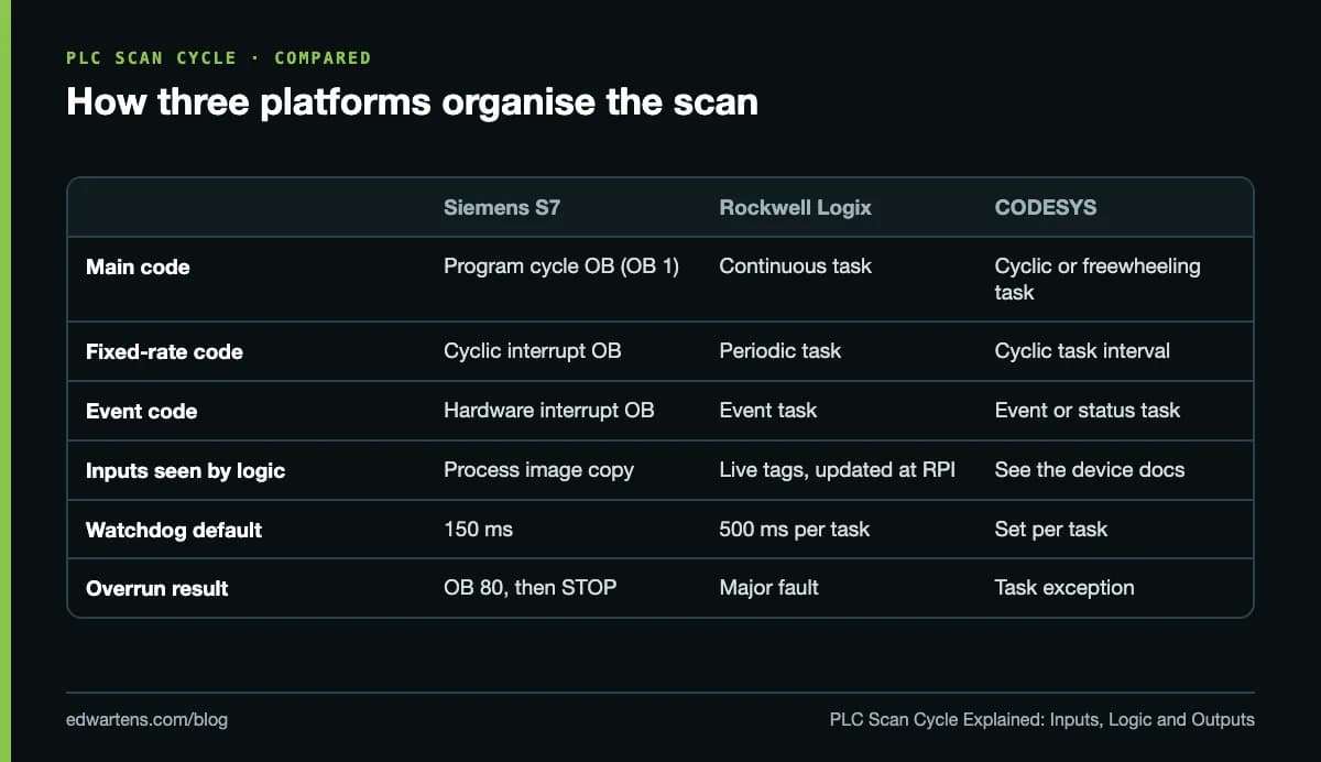
Siemens S7-1200 and S7-1500
The cyclic program lives in program cycle OBs, normally OB 1, run in OB number order. Fixed-rate code goes in a cyclic interrupt OB, which runs at a higher priority and independently of the cycle length; hardware interrupt OBs react to events such as an input edge. On the S7-1500 these are OB 30 to OB 38 and OB 40 to OB 47.
The CPU monitors the cycle against a maximum cycle time, 150 ms by default on both families (1 to 6000 ms on the S7-1200). An overrun calls the time error OB 80, or stops the CPU if there is no OB 80, and a second overrun in the same cycle stops it regardless. On the S7-1500, communication may use up to 50% of the CPU by default, so Siemens warns the actual cycle can be up to twice as long as without communication.
Rockwell Logix 5000
A ControlLogix or CompactLogix controller organises code into tasks. The Tasks, Programs, and Routines manual allows at most one continuous task, which restarts immediately after each full scan and uses whatever CPU time is left. A periodic task interrupts it at a set period (0.1 ms to 2000 s, default 10 ms), and an event task runs on a trigger such as a digital input change or an EVENT instruction.
The big difference is the I/O. Rockwell's General Instructions reference states that I/O module data updates asynchronously to the execution of logic, so an input can change between two references in the same scan. Modules send data at their requested packet interval (RPI), 0.2 to 750 ms. If a routine needs one value throughout, copy the input to a buffer tag first.
Every task has a watchdog, 1 to 2,000,000 ms with a default of 500 ms, including time spent interrupted by other tasks; exceeding it is a major fault. The older SLC 500 family (RSLogix 500) keeps one program watchdog in status word S:3H, 100 ms by default (SLC 500 instruction set reference).
CODESYS
According to the CODESYS online help, a task can be cyclic (restarted after a set interval), freewheeling (restarted in a continuous loop), or started by an event or a status variable. Priorities run from 0 to 31, with 0 the highest, and each task can have a watchdog that halts it with an exception. Configuration elements like these are defined in IEC 61131-3:2025 alongside the languages.
Why can a PLC miss a short input pulse?
Because inputs are sampled, not watched. If a sensor turns on and off between two input reads, the program never sees it. Rockwell's tasks manual uses this exact case: a proximity sensor on for only a short pulse, which the continuous task might miss. Its answer is an event task triggered by a change of state on the input module; the Siemens equivalent is a hardware interrupt OB, which Siemens advises using for a few selected events only.
Edge instructions share the limit, because a rising-edge contact compares the bit with its value in the previous scan. To be sure of catching a signal in cyclic code, it must stay on for longer than the longest gap between two input reads. Shorter signals need an interrupt, an event task or a high-speed counter.
Worked example: estimating cycle and response time
Siemens publishes figures to estimate a cycle by hand. Using its 02/2014 tables for a CPU 1511-1 PN, take a program with 32 words of central input data, 32 words of output data, 20,000 bit operations and 1,000 floating-point operations:
| Item | Siemens figure (CPU 1511-1 PN) | Example time |
|---|---|---|
| Input image update | 35 µs base load + 9 µs per word × 32 | 323 µs |
| Bit operations | 60 ns typical × 20,000 | 1,200 µs |
| Floating-point operations | 384 ns typical × 1,000 | 384 µs |
| Output image update | 35 µs base load + 9 µs per word × 32 | 323 µs |
| Cycle without communication | Sum | about 2.2 ms |
| With the default 50% communication load | Up to twice the sum | up to about 4.5 ms |
The response time is then one to two cycles: about 2.2 ms at best and 9 ms at worst here, plus the module delays from their data sheets. Treat this as a method, not a prediction: the figures come from a 2014 manual for one CPU, and real programs also call blocks and communication instructions. Measure to confirm.
How do you measure PLC scan time?
| Platform | Where to look online | From inside the program |
|---|---|---|
| Siemens TIA Portal | Online tools task card: shortest, current and longest cycle time | RT_INFO for statistics, RUNTIME to time a section |
| Rockwell Studio 5000 (Logix) | Task Properties, Monitor tab (also shows overlaps) | GSV on the TASK object: LastScanTime and MaxScanTime, in microseconds |
| Rockwell RSLogix 500 (SLC 500) | Status file in the data monitor | S:3L current scan, S:22 maximum observed scan, in 10 ms units |
| CODESYS | Task configuration, Monitor tab | Last, average, maximum and minimum cycle time and jitter, in microseconds |
Whatever the platform, watch the maximum. A program that peaks when a recipe loads or a message arrives is the one that trips a watchdog on site.
How do you reduce PLC scan time?
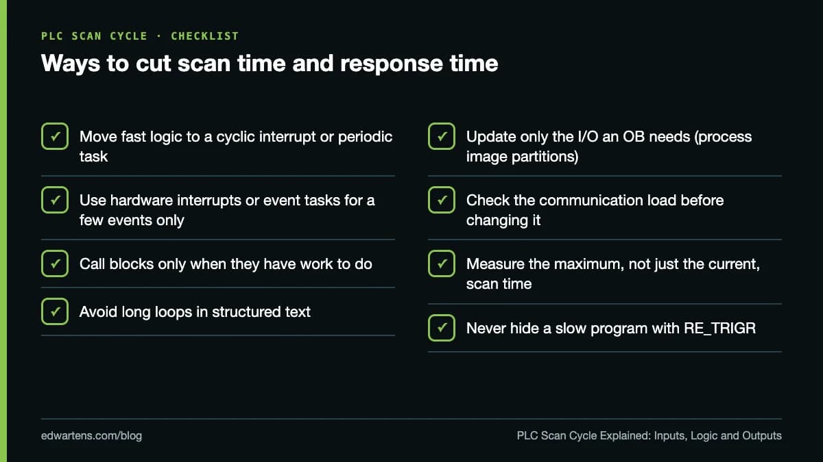
- Split by response need. Siemens recommends moving parts with tight response requirements into higher-priority OBs with shorter cycles; on Logix, use a periodic task.
- Do not make everything urgent. Rockwell warns that too many tasks can make the continuous task too slow and cause overlaps.
- Update only what you use. An S7-1500 offers 32 process image partitions, so an OB can update just its own I/O.
- Skip unneeded work. Siemens lists loops and conditional block calls among the causes of varying cycle time; call blocks only when they have work to do.
- Keep the default communication load unless you have measured, as Siemens advises.
Where to practise
The free Siemens TIA Portal: Organisation Blocks, Interrupts and Timers course covers OB 1, cyclic interrupts and time errors. CODESYS and IEC 61131-3 Programming lets you build tasks on a free soft PLC, and Allen-Bradley RSLogix 500 and MicroLogix covers the Rockwell side. Then read our guides to PLC timers and structured text, and our ladder logic symbols cheat sheet.
All the learning is free. The optional EDWartens Certificate of Completion is a one-off US$8.99; it is our own certificate, not a Siemens, Rockwell or CODESYS credential, it is not accredited, and anyone can check it at edwartens.com/verification.
Take the free course
 Free
FreePLC programming · Beginner · Free
Siemens TIA Portal in Three Hours
 Free
FreePLC programming · Intermediate · Free
Siemens TIA Portal: Organisation Blocks, Interrupts and Timers
 Free
FreePLC programming · Beginner · Free
CODESYS and IEC 61131-3 Programming
 Free
FreePLC programming · Beginner · Free
Allen-Bradley RSLogix 500 and MicroLogix
Questions
What is a PLC scan cycle?
A PLC scan cycle is the loop a PLC repeats while it is in RUN: read all inputs into memory, execute the program from top to bottom, write the results to the outputs, then handle communication and diagnostics. The time one pass takes is the scan time, which Siemens calls the cycle time.
What is the difference between scan time and response time?
Scan time is how long one pass of the program takes. Response time is how long it takes from an input changing to the output it controls changing. Siemens states that the CPU response time varies between one and two cycle times, plus the delays of the input and output modules and any network update time.
What happens if the PLC scan time is too long?
The watchdog trips. On Siemens S7-1200 and S7-1500 CPUs the default maximum cycle time is 150 ms; exceeding it calls the time error OB 80 or stops the CPU, and a second overrun in the same cycle stops it regardless. On Rockwell Logix controllers each task has a watchdog, 500 ms by default, and exceeding it causes a major fault.
How do I check the scan time in TIA Portal?
Go online with the CPU and open the Online tools task card on the right of TIA Portal; the cycle time section shows the shortest, current and longest cycle time. Inside the program, the RT_INFO instruction returns cycle statistics and the RUNTIME instruction times a section of code.
Does an Allen-Bradley ControlLogix use a process image?
Not in the Siemens sense. Rockwell's Logix documentation states that I/O module data updates asynchronously to the execution of logic, at each module's requested packet interval (RPI). If a routine needs the same input value throughout, copy the input to a buffer tag at the start of the routine or use program parameters, which buffer the data automatically.
Can a PLC miss a short input signal?
Yes. Cyclic code only sees an input when the inputs are read, so a pulse that starts and ends between two reads is never seen. For very short signals use an event task on Rockwell, a hardware interrupt OB on Siemens, or a high-speed counter or pulse-capturing input module.
Sources
- Siemens: SIMATIC S7-1500 Cycle and response times, Function Manual, 02/2014 (A5E03461504-02), read 11 October 2026
- Siemens: S7-1200 Programmable controller System Manual, 11/2011 (A5E02486680-05), read 11 October 2026
- Rockwell Automation: Logix 5000 Controllers Tasks, Programs, and Routines, publication 1756-PM005M-EN-P (September 2025)
- Rockwell Automation: Logix 5000 Controllers General Instructions Reference Guide, publication 1756-RM018A-EN-P (September 2025)
- Rockwell Automation: SLC 500 Instruction Set Reference Manual, publication 1747-RM001G-EN-P (November 2008)
- CODESYS online help: Object: Task, read 11 October 2026
- CODESYS online help: Task Configuration, Monitor tab, read 11 October 2026
- IEC: IEC 61131-3:2025 Programmable controllers, Part 3: Programming languages (edition 4.0, 22 May 2025)
- Instrumentation Tools: PLC Scan Cycle Explained (YouTube)
Written by the EDWartens engineering team for general education. Product names are trademarks of their owners; mentioning them does not imply endorsement. Prices and terms of other providers were checked on the date shown and can change.

AI Copilots for PLC Programming in 2026: Siemens, Rockwell, CODESYS and Beckhoff

How Long Does It Take to Learn PLC Programming? A Week-by-Week Plan

CODESYS for Free: Learn IEC 61131-3 Without Buying a PLC

Your First S7-1200 Program in TIA Portal and PLCSIM (Video)

Free PLC Simulators Compared: PLCSIM, CCW, CODESYS, OpenPLC and Browser Simulators

Start/Stop Seal-In Circuit in Ladder Logic, Explained Rung by Rung (Video)