LADDER SYMBOLS
Ladder Logic Symbols: A Cheat Sheet with Examples
Every common ladder logic symbol with its Rockwell mnemonic, Siemens LAD name and IEC 61131-3 name, why an NC stop button uses an XIC contact, and five rung-by-rung examples: seal-in, interlock, latch, timer and counter.

Ladder logic symbols are the contacts, coils and instruction boxes a PLC rung is built from. The three you use most are the normally open contact -| |-, which passes power when its bit is 1; the normally closed contact -|/|-, which passes power when its bit is 0; and the coil -( )-, which writes the result of the rung to a bit. Set (latch) and reset (unlatch) coils, edge contacts and one-shots, and boxes for timers, counters, comparisons, maths and moves cover almost everything else.
Checked on 11 October 2026 against the Rockwell Automation, Siemens, CODESYS and Phoenix Contact documents listed under this post.
Why do the same symbols have different names?
Ladder diagram is one of the two graphical languages in IEC 61131-3:2025, the fourth edition of the PLC languages standard, published on 22 May 2025. The drawings look almost identical on every platform, but the names do not. Rockwell uses three-letter mnemonics such as XIC and OTE, Siemens uses descriptive names such as "normally open contact", and IEC-style tools such as CODESYS and PLCnext Engineer use the standard's names, such as "positive transition-sensing contact".
In plain text, contacts are often written with square brackets, ] [ and ]/[, which is how Rockwell's own SLC 500 manual prints XIC and XIO. The tables below use that form.
In this video, Tim Wilborne explains why PLC instructions are not really "normally open" and "normally closed", a frequent source of confusion with these symbols. It is one of the lessons in our free Allen-Bradley RSLogix 500 and MicroLogix course, and it is worth watching before the stop-button section below.
Ladder logic symbols cheat sheet: contacts and coils
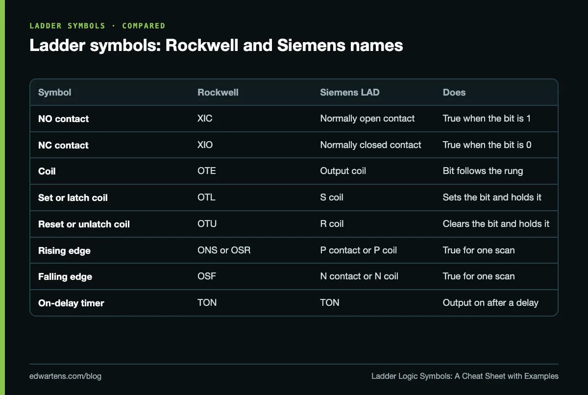
| Symbol | IEC 61131-3 name | Rockwell Logix | Siemens LAD | What it does |
|---|---|---|---|---|
| ] [ | Normally open contact | XIC, Examine If Closed | Normally open contact | Passes power when the bit is 1 |
| ]/[ | Normally closed contact | XIO, Examine If Open | Normally closed contact | Passes power when the bit is 0 |
| ( ) | Coil | OTE, Output Energize | Output coil | Bit is 1 while the rung is true, 0 when it is false |
| (/) | Negated coil | No Logix bit instruction | Inverted output coil | Bit is 0 while the rung is true, 1 when it is false |
| (S) or (L) | Set coil | OTL, Output Latch | S (set) coil | Sets the bit to 1 and leaves it there |
| (R) or (U) | Reset coil | OTU, Output Unlatch | R (reset) coil | Clears the bit to 0 and leaves it there |
| ]P[ | Positive transition-sensing contact | ONS, One Shot (acts on the rung) | P contact | True for one scan when the signal goes from 0 to 1 |
| ]N[ | Negative transition-sensing contact | None as a contact | N contact | True for one scan when the signal goes from 1 to 0 |
| (P) | Positive transition-sensing coil | OSR, One Shot Rising | P coil | Writes 1 for one scan when the rung goes true |
| (N) | Negative transition-sensing coil | OSF, One Shot Falling | N coil | Writes 1 for one scan when the rung goes false |
The Rockwell definitions come from the Logix 5000 General Instructions reference (September 2025), the Siemens names from the S7-1200 system manual, and the IEC names from the PLCnext Engineer and CODESYS help. Siemens also has a NOT contact, which simply inverts the power flow passing through it.
Three rules make any rung readable:
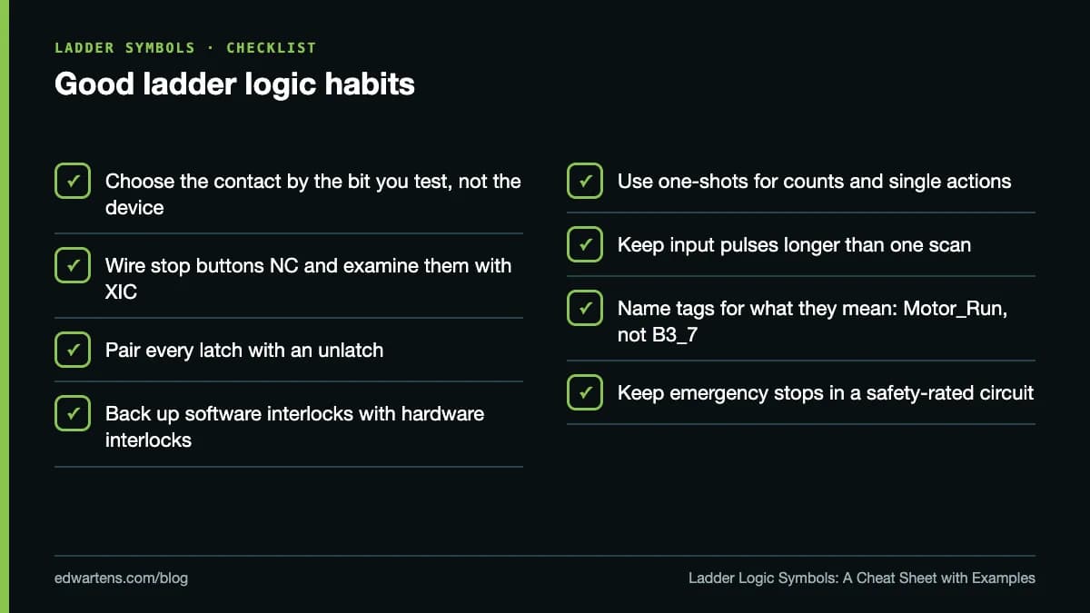
- Series means AND, parallel means OR. Contacts in series must all pass power; in parallel, any one branch is enough.
- Coils go on the right. CODESYS adds that several coils in one network can only be arranged in parallel.
- The PLC reads rungs in order, every scan. A rung near the top acts on values that rungs further down have not updated yet. Our PLC scan cycle guide explains why that matters.
What do the box symbols mean?
| Box | Rockwell Logix | Siemens LAD | Key detail |
|---|---|---|---|
| On-delay timer | TON | TON | Logix PRE and ACC are in milliseconds; done bit .DN. Siemens uses PT, ET and output Q |
| Off-delay timer | TOF | TOF | Times while the rung is false, then switches the output off |
| Count up | CTU | CTU | Adds 1 on each false-to-true transition of the rung |
| Count down | CTD | CTD | Subtracts 1 on each false-to-true transition |
| Reset | RES | R input on CTU and CTUD | Clears the accumulated value and status bits |
| Compare | EQ, GT, LT and others | Compare contact (==, >, < and others) | Siemens draws comparisons as contacts |
| Add | ADD | ADD | Adds source A to source B |
| Move | MOVE | MOVE | Copies a value to another tag or address |
One change catches out people who learnt on older Rockwell software: in Logix Designer version 36, several mnemonics were renamed. EQU became EQ, GRT became GT, LES became LT, NEQ became NE and MOV became MOVE. Rockwell's timer time base is always 1 ms, so a 2-second TON has a preset of 2000. For the timer family in depth, see our guide to TON, TOF and TP timers, and for counters, CTU, CTD and CTUD.
Why is a stop button programmed with a normally open contact?
Because an examine-if-closed contact (XIC) tests a bit, not a device. It is true when its bit is 1, whatever is wired to the input. The Rockwell reference says exactly that: XIC and XIO examine the data bit to set or clear the rung condition.
Stop buttons are usually wired with normally closed contacts, so a broken wire or a lost supply looks the same as a press and stops the machine. With an NC stop button, the input bit is 1 when nobody is touching it:
| Stop button (wired NC) | Input bit | XIC Stop_PB | XIO Stop_PB |
|---|---|---|---|
| Not pressed | 1 | True: the motor may run | False: the motor cannot start |
| Pressed | 0 | False: the motor stops | True: the motor could start |
| Wire broken | 0 | False: the motor stops | True |
So the correct instruction for an NC stop button is XIC, the symbol that looks "normally open". Use XIO and the machine will only run while the stop button is held in. Rockwell's SLC 500 manual gives a matching example for XIO: a normally closed motor overload contact wired to an input. XIO on that input is true only when the overload has opened. Pick the contact by the state of the bit you want to test, never by the symbol on the wiring diagram. Emergency stops belong in a hard-wired or safety-rated circuit, not only in standard PLC logic.
Five ladder logic examples, rung by rung
The tag names below are examples. Start_PB is a normally open push button, and Stop_PB is a normally closed one.
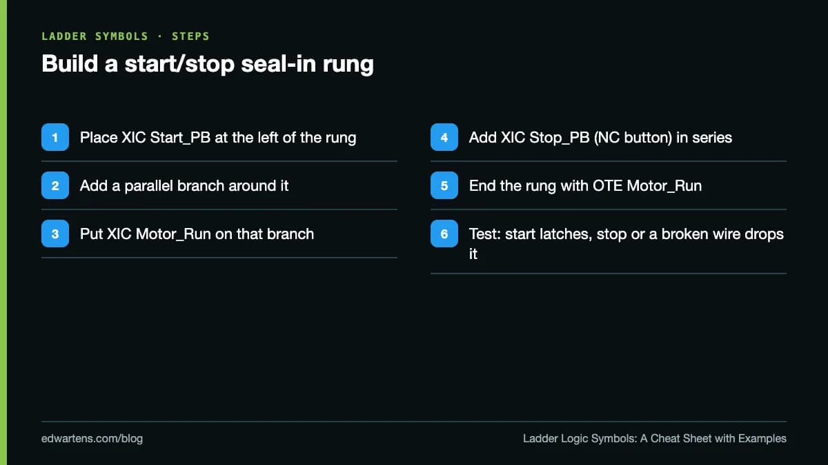
1. Start/stop with a seal-in
| Position | Instruction | Tag | Why |
|---|---|---|---|
| Branch A | XIC | Start_PB | Pressing start powers the rung |
| Branch B, parallel to A | XIC | Motor_Run | The motor's own bit holds the rung on after start is released |
| In series | XIC | Stop_PB | NC button: opens the rung when pressed |
| Output | OTE | Motor_Run | Runs the motor |
In Siemens LAD the same rung uses two normally open contacts in parallel, a normally open contact for the stop input and an output coil. Our start/stop ladder logic walkthrough builds it step by step.
2. Forward/reverse interlock
Rung 1 is a seal-in for Fwd_Run with an extra XIO Rev_Run in series. Rung 2 is its mirror: a seal-in for Rev_Run with XIO Fwd_Run in series. Each direction can only start while the other is off. Add an electrical interlock on the contactors as well, because the program cannot stop a welded contactor.
3. Latch and unlatch
Rung 1: XIC Start_PB, then OTL Pump. Rung 2: XIO Stop_PB, then OTU Pump. Rung 3: XIC Low_Level, then OTU Pump. The pump stays on after start is released because OTL only ever sets the bit; it never clears it when the rung goes false. Note the difference after a mode change: the Logix reference says an OTE bit is cleared during prescan, while OTL does nothing on prescan, so a latched bit keeps its last value. Use latches deliberately and always pair them with an unlatch.
4. Delayed start with a timer
Rung 1: XIC Run_Request, then TON Horn_Delay with a preset of 5000 (5 seconds in Logix). Rung 2: XIC Run_Request, XIO Horn_Delay.DN, then OTE Warning_Horn. Rung 3: XIC Horn_Delay.DN, then OTE Conveyor. The horn sounds for five seconds, then the conveyor starts. In TIA Portal, set PT to T#5S and use the timer's Q output instead of .DN.
5. Counting cartons
Rung 1: XIC Box_Sensor, then CTU Box_Count with a preset of 12. Rung 2: XIC Box_Count.DN, then OTE Carton_Full. Rung 3: XIC Reset_PB, then RES Box_Count. CTU counts each false-to-true transition, so a sensor held on counts once. The sensor pulse must last longer than one scan, or the PLC may never see it.
Where to practise
Rockwell users can try these rungs in the free Allen-Bradley Studio 5000 course, and Siemens users in Siemens TIA Portal. CODESYS and IEC 61131-3 Programming uses the IEC names on a free soft PLC. To see where ladder fits among the other languages, read our guide to the top PLC programming languages.
All the learning is free. The optional EDWartens Certificate of Completion is a one-off US$8.99; it is our own certificate, not a Rockwell, Siemens or CODESYS credential, it is not accredited, and anyone can check it at edwartens.com/verification.
Take the free course


Questions
What are the basic ladder logic symbols?
The basic symbols are the normally open contact (-| |-), true when its bit is 1; the normally closed contact (-|/|-), true when its bit is 0; and the coil (-( )-), which writes the rung result to a bit. Most programs also use set and reset coils, one-shots, and boxes for timers, counters, comparisons, maths and moves.
What is the difference between XIC and XIO?
XIC (Examine If Closed) is true when its bit is 1, and XIO (Examine If Open) is true when its bit is 0. Both test a bit in the controller's memory, not the physical contact wired to the input. They are Rockwell's names for the normally open and normally closed contacts.
Why is a normally closed stop button programmed with a normally open contact?
A normally closed stop button keeps its input bit at 1 until it is pressed, so the rung needs an XIC (normally open) contact that is true while the bit is 1. Pressing the button, or a broken wire, drops the bit to 0 and opens the rung. Using XIO instead would let the machine run only while the stop button is held in.
What is the difference between OTE and OTL?
OTE (Output Energize) sets its bit to 1 while the rung is true and clears it to 0 when the rung is false. OTL (Output Latch) sets the bit to 1 when the rung is true and leaves it there when the rung goes false, until an OTU (Output Unlatch) clears it. Siemens calls the latching pair the S and R coils.
What does ONS mean in ladder logic?
ONS is Rockwell's One Shot instruction. It makes the rest of the rung true for one scan each time the conditions before it change from false to true, using a storage bit to remember the previous state. Siemens uses a P contact for the same job, and IEC tools call it a positive transition-sensing contact.
Are ladder logic symbols the same in Siemens and Allen-Bradley?
The drawings are almost the same, but the names differ. Rockwell uses mnemonics such as XIC, XIO, OTE, OTL and OTU, while Siemens TIA Portal uses descriptive names such as normally open contact, output coil and set or reset coil. Siemens also draws comparisons as contacts, while Rockwell uses compare instructions such as EQ and GT.
Sources
- Rockwell Automation: Logix 5000 Controllers General Instructions Reference Guide, publication 1756-RM018A-EN-P (September 2025)
- Rockwell Automation: SLC 500 Instruction Set Reference Manual, publication 1747-RM001G-EN-P (November 2008)
- Siemens: S7-1200 Programmable controller System Manual, 11/2011 (A5E02486680-05), basic instructions, read 11 October 2026
- Phoenix Contact: PLCnext Engineer help, LD language elements (contacts), read 11 October 2026
- Phoenix Contact: PLCnext Engineer help, coils in LD, read 11 October 2026
- CODESYS online help: LD element coil, read 11 October 2026
- CODESYS online help: LD element contact, read 11 October 2026
- IEC: IEC 61131-3:2025 Programmable controllers, Part 3: Programming languages (edition 4.0, 22 May 2025)
- Tim Wilborne: PLC Instructions are not Normally Open and Normally Closed! (YouTube)
Written by the EDWartens engineering team for general education. Product names are trademarks of their owners; mentioning them does not imply endorsement. Prices and terms of other providers were checked on the date shown and can change.
What Is PLC Programming? A Complete Beginner's Guide

AI Copilots for PLC Programming in 2026: Siemens, Rockwell, CODESYS and Beckhoff

Your First S7-1200 Program in TIA Portal and PLCSIM (Video)

How Long Does It Take to Learn PLC Programming? A Week-by-Week Plan

TIA Portal Free Trial and Licences Explained (and What PLCSIM Needs)
Structured Text Programming Tutorial: IF, CASE, Timers (Video)