Level 1 · Free project
Commission the transfer-pump starter
Lock out, prove dead, wire the control circuit to the PLC, restore power and run the pump. A 415 V DOL starter with a 24 V PLC, built the way industrial panels are.
Free with a free account. Runs in your browser.
What you will build
Work order WO-PS-101. Your site team, Commission the P-101 transfer-pump starter.
The starter panel for transfer pump P-101 has arrived from the panel shop with the power circuit and the 24 V supply wired. The control wiring to the PLC is yours.
What you will learn
- Lock out and prove dead, live then dead then live
- Land 19 control conductors from a wiring schedule
- Read the supplied PLC program and match it to your wiring
- Restore power safely, test, and run the FAT
How it goes
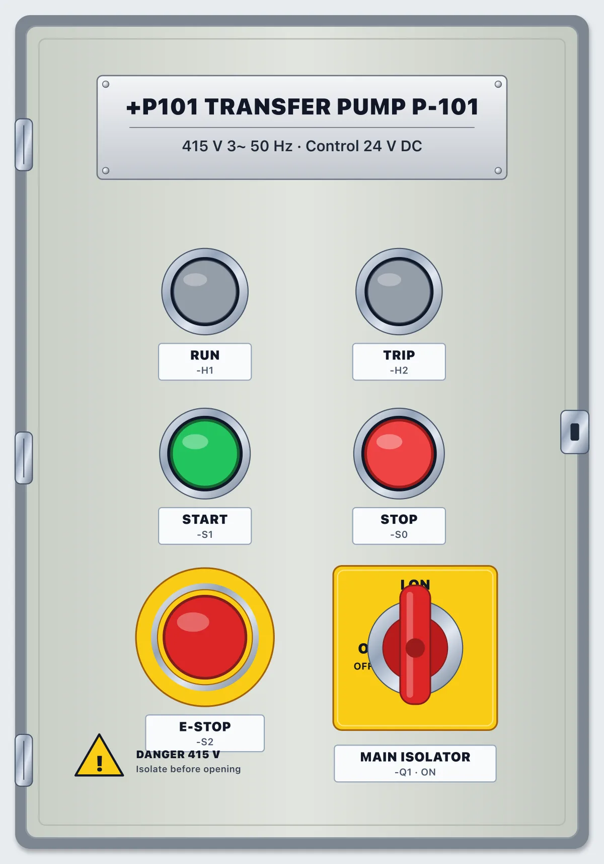
- Lock out the panel at the main isolator Q1: switch OFF, apply your lock and your tag.
- Prove it dead with the meter, live-dead-live: prove the meter on the live incoming terminals, check every conductor on the load side reads 0 V, prove the meter again.
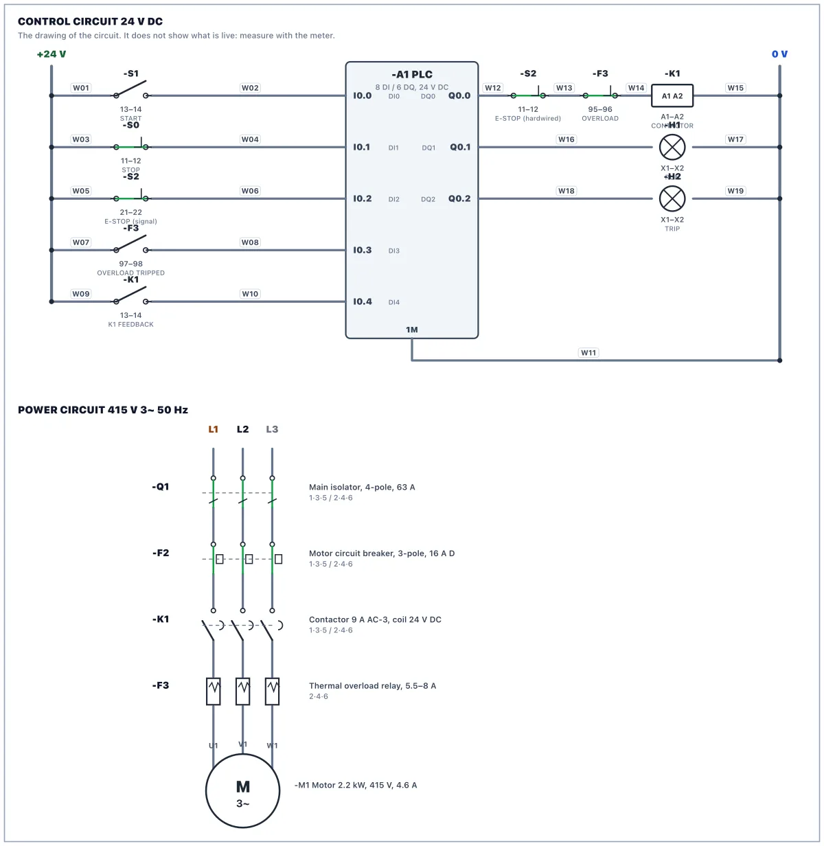
- Wire the 19 conductors of the wiring schedule. One conductor per terminal: X2 has spare bridged terminals for +24 V (1 to 6) and 0 V (7 to 12).
- Read the supplied PLC program. You may improve it, but the tag addresses must match your wiring.
- Restore power: tick the checklist, remove your tag and lock, switch Q1 ON, put the PLC in RUN.
- Test: START runs the pump and fills the day tank, STOP and the E-STOP stop it, an overload trip stops it and lights TRIP, and nothing restarts by itself. Then run the FAT.
Parts in the panel
Main isolator, 4-pole, 63 A
Switches all three phases and neutral. The incoming cable lands on 1, 3, 5, 7: those terminals stay live when it is OFF.
MCB 2-pole, 6 A, C curve: control supply
Feeds the 24 V power supply with 230 V (L1 and N).
MCB 3-pole, 16 A, D curve: motor circuit
Protects the motor circuit against short circuits. The overload relay protects the motor against overload.
Contactor 3-pole, 9 A AC-3, coil 24 V DC, 1 NO aux
Switches the motor. Coil A1(+)/A2(−). The 13 to 14 auxiliary contact tells the PLC the contactor really pulled in.
Thermal overload relay, 5.5 to 8 A
Trips on sustained overcurrent. 95 to 96 (NC) opens and 97 to 98 (NO) closes. Blue button: reset.
Power supply 230 V AC to 24 V DC, 5 A
Its 0 V (−) is bonded to PE at the factory, so 0 V and earth are the same potential.
PLC: compact CPU, 8 DI / 6 DQ, 24 V DC
Inputs I0.0, I0.7 are PNP: 24 V on the terminal turns the input on, with 1M at 0 V. Outputs Q0.0, Q0.5 source 24 V from 3L+.
Terminal strip X2: 24 V DC distribution
Positions 1 to 6 are bridged +24 V, 7 to 12 are bridged 0 V. Top and bottom of each position are the same point.
Terminal strip X1: motor
The motor cable from the plant lands here.
PE bar
Protective earth, bonded to the incoming supply's earth.
Push button START, green, 1 NO
Push button STOP, red, 1 NC
Emergency stop, 2 NC, twist to release
Contact 11 to 12 is hardwired in the coil circuit; 21 to 22 tells the PLC.
Pilot lamp green 24 V: RUNNING
Pilot lamp amber 24 V: OVERLOAD TRIPPED
Motor 3-phase 2.2 kW, 415 V, 4.6 A, driving pump P-101
Questions
- Is it free?
- Yes. The lab is free to use with a free account. There is nothing to buy to open this scenario.
- Do I need to install anything?
- No. It runs in your browser with a 3D panel, a circuit drawing, a meter and a PLC.
- What will I do in Panel Lab 1?
- You wire a control panel, then check your work against an acceptance test.
- How long does it take?
- Plan for one sitting. You can stop and come back.
- Do I need experience?
- No. Each work order says what to do step by step, and hints are there if you get stuck.