Level 9 · Free project
Commission the pneumatic pusher station
A 5/2 double-solenoid valve and a double-acting cylinder: wire the coils, hose the air circuit with its speed controls, read the reed switches, and keep the gate interlock hardwired.
Free with a free account. Runs in your browser.
What you will build
Work order WO-PS-901. Your site team, Commission the pneumatic pusher station.
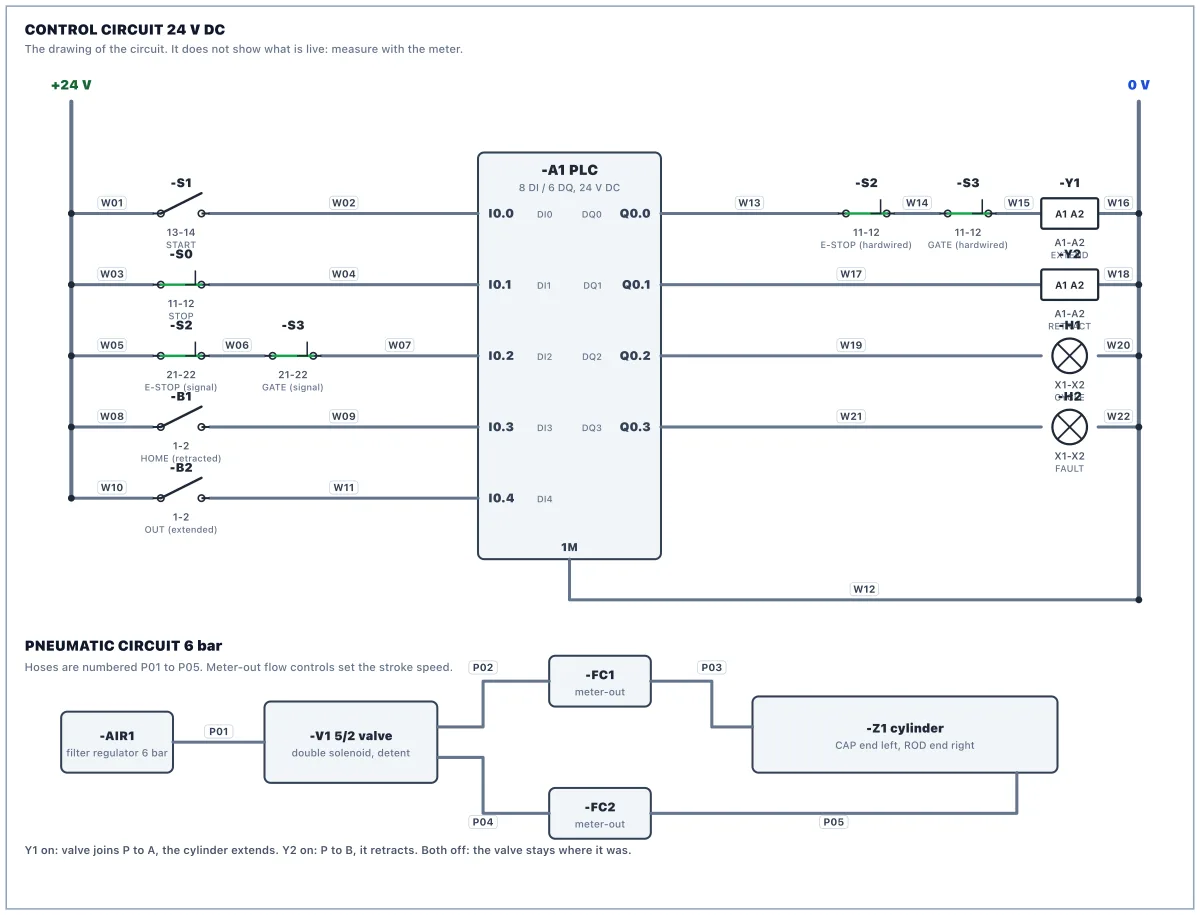
Vaigai Foods, Madurai. Carton diverter PU-901 pushes cartons off the line with a double-acting cylinder Z1, driven by a 5/2 double-solenoid valve V1: coil Y1 extends, coil Y2 retracts, and the valve keeps its position when both are off. Reed switches B1 (home) and B2 (extended) sit on the cylinder. A guard gate S3 and an E-STOP S2 protect the operator. The control panel +F901 has arrived with the 24 V supply and the PLC supply wired. The field wiring and the air circuit are yours.
What you will learn
- Lock out and prove dead, live then dead then live
- Land 27 control conductors from a wiring schedule
- Read the supplied PLC program and match it to your wiring
- Restore power safely, test, and run the FAT
How it goes
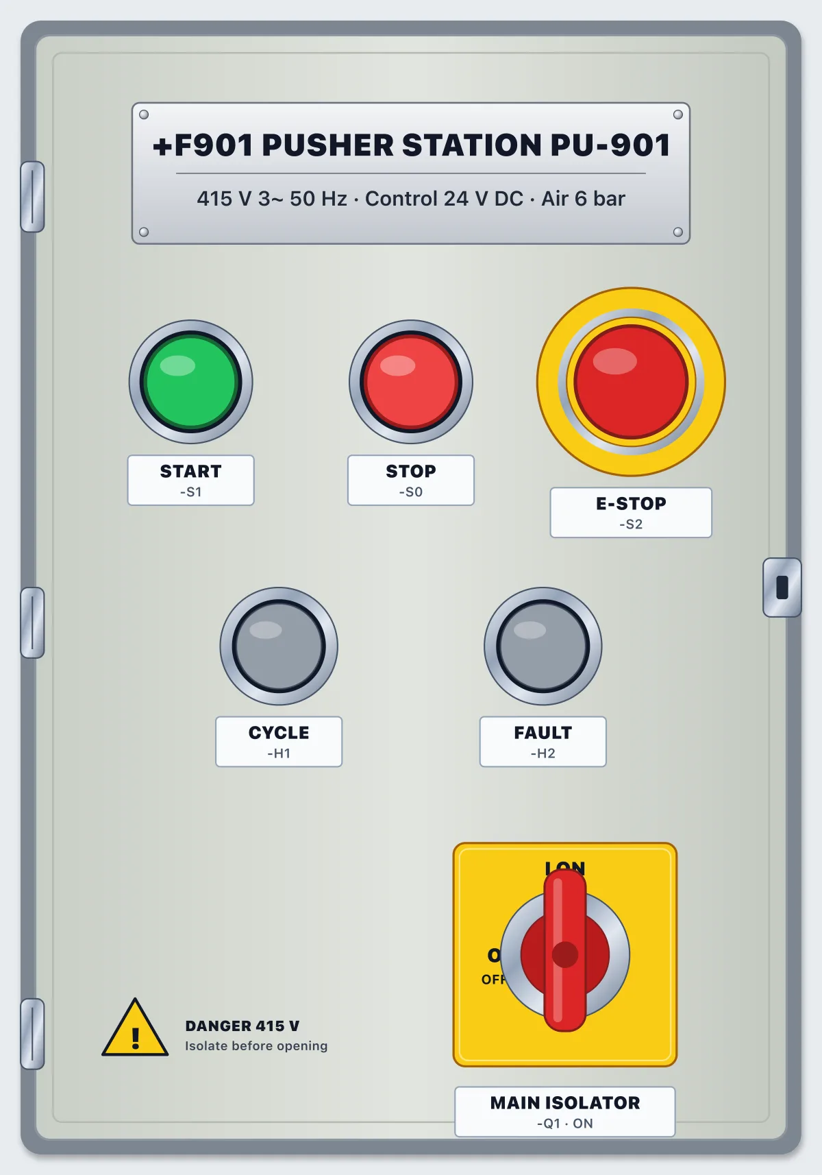
- Lock out the panel at the main isolator Q1: switch OFF, apply your lock and your tag.
- Prove it dead with the meter, live-dead-live. Treat the air as a stored energy too: the cylinder can move when a coil is energised, so keep clear of it.
- Wire the 22 conductors of the wiring schedule. The extend coil Y1 is fed through the E-STOP and the gate contacts in series, hardwired, so that no program can extend the cylinder with the gate open. The retract coil Y2 is not, because retracting is the safe move.
- Hose the air circuit, P01 to P05. Fit the flow controls meter-out: the hose from the valve goes to the IN of the flow control and its OUT goes to the cylinder. A cylinder with no speed control slams into its end cap.
- Read the supplied PLC program. It starts a cycle from START with the cylinder home, extends until B2, dwells, retracts and ends at home. A move over 4 s is a fault.
- Restore power: tick the checklist, remove your tag and lock, switch Q1 ON, put the PLC in RUN.
- Test: force each coil, check the reed switches, time the strokes, run a cycle, open the gate during a stroke and press the E-STOP. Then run the FAT.
Parts in the panel
Main isolator, 4-pole, 63 A
Switches all three phases and neutral. The incoming cable lands on 1, 3, 5, 7: those terminals stay live when it is OFF.
MCB 2-pole, 6 A, C curve: control supply
Feeds the 24 V power supply with 230 V (L1 and N).
Power supply 230 V AC to 24 V DC, 5 A
Its 0 V (−) is bonded to PE at the factory, so 0 V and earth are the same potential.
PLC: compact CPU, 8 DI / 6 DQ, 24 V DC
Inputs I0.0-I0.7 are PNP: 24 V on the terminal turns the input on, with 1M at 0 V. Outputs Q0.0-Q0.5 source 24 V from 3L+.
Terminal strip X2: 24 V DC distribution, 16 positions
Positions 1 to 8 are bridged +24 V, 9 to 16 are bridged 0 V. Top and bottom of each position are the same point.
PE bar
Protective earth, bonded to the incoming supply's earth.
Push button START, green, 1 NO
Push button STOP, red, 1 NC
Emergency stop, 2 NC, twist to release
Contact 11-12 is hardwired in the coil circuit; 21-22 tells the PLC.
Pilot lamp green 24 V: CYCLE RUNNING
Pilot lamp amber 24 V: FAULT
Filter regulator, 6 bar
The compressed air supply to the station.
5/2 solenoid valve, double solenoid, detent
Y1 shifts it so that P is joined to A (A to the cap end, B exhausts). Y2 shifts it so that P is joined to B. With both off it stays where it was.
Solenoid coil Y1, 24 V DC: EXTEND
Pilot coil on the A side of V1. Wired through the E-STOP and the guard gate contacts.
Solenoid coil Y2, 24 V DC: RETRACT
Pilot coil on the B side of V1. Retracting is the safe move, so it is not through the gate.
Flow control FC1, meter-out, needle set to 30 %
Fitted at the cap end: free flow in, throttled flow out. It sets the speed of the retract stroke.
Flow control FC2, meter-out, needle set to 30 %
Fitted at the rod end: free flow in, throttled flow out. It sets the speed of the extend stroke.
Cylinder Z1, double-acting, 32 mm bore, 100 mm stroke
Air on CAP pushes the rod out, air on ROD pulls it in.
Reed switch B1, NO: closed at home (retracted)
Reed switch B2, NO: closed at the extended end
Guard gate interlock switch, 2 NC (11-12 safety, 21-22 signal)
Both contacts open when the gate is opened. 11-12 is hardwired in the extend coil circuit, 21-22 tells the PLC.
Questions
- Is it free?
- Yes. The lab is free to use with a free account. There is nothing to buy to open this scenario.
- Do I need to install anything?
- No. It runs in your browser with a 3D panel, a circuit drawing, a meter and a PLC.
- What will I do in Panel Lab 9?
- You wire a control panel, then check your work against an acceptance test.
- How long does it take?
- Plan for one sitting. You can stop and come back.
- Do I need experience?
- No. Each work order says what to do step by step, and hints are there if you get stuck.