Level 6 · Free project
Commission the sorting station sensors
Wire a 3-wire PNP proximity sensor and a 3-wire NPN photo-eye to the right input groups of a PLC, and prove each one: brown, blue, black, and the sinking and sourcing commons.
Free with a free account. Runs in your browser.
What you will build
Work order WO-PS-601. Your site team, Commission the sorting station sensors.
Coastal Packaging Works. Sorting station SS-601 sits on conveyor CV-601 (motor 0.75 kW, 415 V, 1.9 A, direct-on-line starter). Sensor B1 is an inductive proximity sensor, 3-wire PNP, that sees the metal carrier tray arrive at the stop. Sensor B2 is a diffuse photoelectric sensor, 3-wire NPN, that sees a carton at the diverter. The PLC has two input groups: I0.0 to I0.5 on the common 1M, and I0.6 and I0.7 on the common 2M. The panel +S601 has arrived with the power circuit and the 24 V supply wired. The control wiring is yours.
What you will learn
- Lock out and prove dead, live then dead then live
- Land 26 control conductors from a wiring schedule
- Read the supplied PLC program and match it to your wiring
- Restore power safely, test, and run the FAT
How it goes
- Lock out the panel at the main isolator Q1: switch OFF, apply your lock and your tag.
- Prove it dead with the meter, live-dead-live.
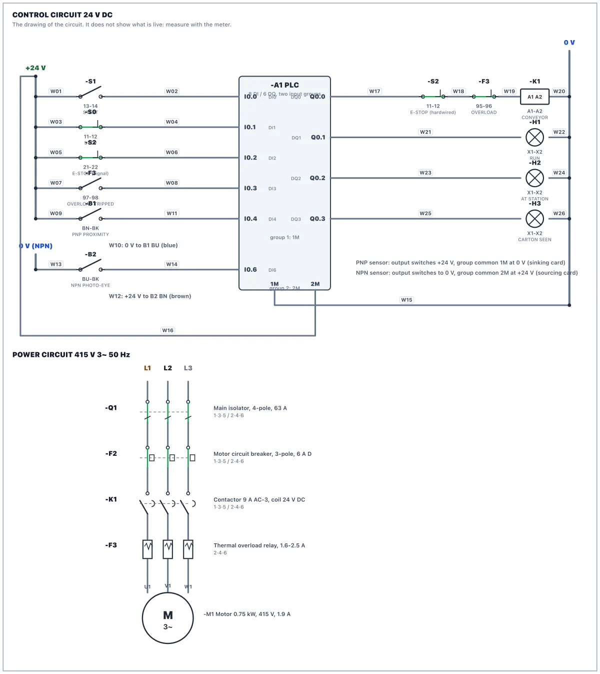
- Wire the 26 conductors of the wiring schedule. A 3-wire sensor has brown (BN) for +24 V, blue (BU) for 0 V and black (BK) for the signal. A PNP sensor switches +24 V onto its black wire, so it goes to a group whose common is at 0 V (a sinking card). An NPN sensor switches its black wire to 0 V, so it goes to a group whose common is at +24 V (a sourcing card).
- Common 1M goes to 0 V (W15) for the PNP group. Common 2M goes to +24 V (W16) for the NPN group. Do not put the NPN sensor on a 1M input.
- Read the supplied PLC program. The carrier at B1 stops the conveyor. Sensors are not safety devices: the E-STOP stays hardwired in the coil circuit.
- Restore power: tick the checklist, remove your tag and lock, switch Q1 ON, put the PLC in RUN.
- Test: watch the sensor inputs with nothing in front of the sensors, then hold each target in front of its sensor (press and hold the target button on the sensor). Then run the FAT.
Parts in the panel
Main isolator, 4-pole, 63 A
Switches all three phases and neutral. The incoming cable lands on 1, 3, 5, 7: those terminals stay live when it is OFF.
MCB 2-pole, 6 A, C curve: control supply
Feeds the 24 V power supply with 230 V (L1 and N).
MCB 3-pole, 6 A, D curve: motor circuit
Protects the motor circuit against short circuits. The overload relay protects the motor against overload.
Contactor 3-pole, 9 A AC-3, coil 24 V DC
Switches the conveyor motor. Its coil gets 24 V from Q0.0 through the E-STOP and the overload contact.
Thermal overload relay, 1.6-2.5 A, set 1.9 A
Trips on sustained overcurrent. 95-96 (NC) opens and 97-98 (NO) closes. Blue button: reset.
Power supply 230 V AC to 24 V DC, 5 A
Its 0 V (−) is bonded to PE at the factory, so 0 V and earth are the same potential.
PLC: compact CPU, 8 DI / 6 DQ, 24 V DC, two input groups
Group 1 is I0.0 to I0.5 on 1M. Group 2 is I0.6 and I0.7 on 2M. With the common at 0 V a group reads PNP sensors (sinking card). With the common at +24 V it reads NPN sensors (sourcing card). Outputs Q0.0 to Q0.5 source 24 V from 3L+.
Terminal strip X2: 24 V DC distribution
Positions 1-6 are bridged +24 V, 7-12 are bridged 0 V. Top and bottom of each position are the same point.
Terminal strip X1: motor
The motor cable from the plant lands here.
PE bar
Protective earth, bonded to the incoming supply's earth.
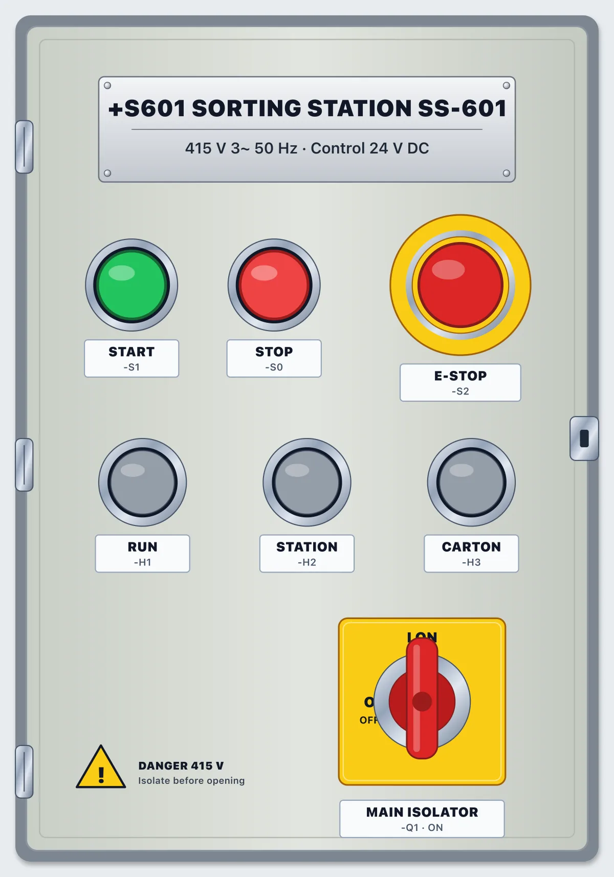
Push button START, green, 1 NO
Push button STOP, red, 1 NC
Emergency stop, 2 NC, twist to release
Contact 11-12 is hardwired in the coil circuit; 21-22 tells the PLC.
Pilot lamp green 24 V: RUNNING
Pilot lamp amber 24 V: CARRIER AT STATION
Pilot lamp white 24 V: CARTON SEEN
Motor 3-phase 0.75 kW, 415 V, 1.9 A, driving conveyor CV-601
Inductive proximity sensor B1, 3-wire PNP, NO, M12, 24 V DC
Sees the metal carrier tray at the stop. Brown +24 V, blue 0 V, black signal. When it detects, its black wire switches +24 V (PNP). It needs an input group whose common is at 0 V.
Photoelectric sensor B2, diffuse, 3-wire NPN, NO, 24 V DC
Sees a carton at the diverter. Brown +24 V, blue 0 V, black signal. When it detects, its black wire switches to 0 V (NPN). It needs an input group whose common is at +24 V.
Questions
- Is it free?
- Yes. The lab is free to use with a free account. There is nothing to buy to open this scenario.
- Do I need to install anything?
- No. It runs in your browser with a 3D panel, a circuit drawing, a meter and a PLC.
- What will I do in Panel Lab 6?
- You wire a control panel, then check your work against an acceptance test.
- How long does it take?
- Plan for one sitting. You can stop and come back.
- Do I need experience?
- No. Each work order says what to do step by step, and hints are there if you get stuck.