Level 5 · Free project
Commission the overhead tank pump (Hand/Off/Auto)
Fill an overhead tank between two float switches, with a Hand/Off/Auto selector that works even when the PLC is stopped, and never bypasses the E-STOP or the overload.
Free with a free account. Runs in your browser.
What you will build
Work order WO-PS-501. Your site team, Commission the overhead tank pump (Hand/Off/Auto).
Sunrise Apartments, Bengaluru. Fill pump P-501 lifts water from the sump to overhead tank OHT-501, and the building draws the tank down all day. The motor is 3.7 kW, 415 V, 7.5 A. Two float switches in the tank, B1 at 20 % and B2 at 90 %, go to the PLC. The plant engineer wants a Hand/Off/Auto selector so that the caretaker can run the pump by hand if the PLC is out of service. The starter panel +P501 has arrived with the power circuit and the 24 V supply wired. The control wiring is yours.
What you will learn
- Lock out and prove dead, live then dead then live
- Land 25 control conductors from a wiring schedule
- Read the supplied PLC program and match it to your wiring
- Restore power safely, test, and run the FAT
How it goes
- Lock out the panel at the main isolator Q1: switch OFF, apply your lock and your tag.
- Prove it dead with the meter, live-dead-live.
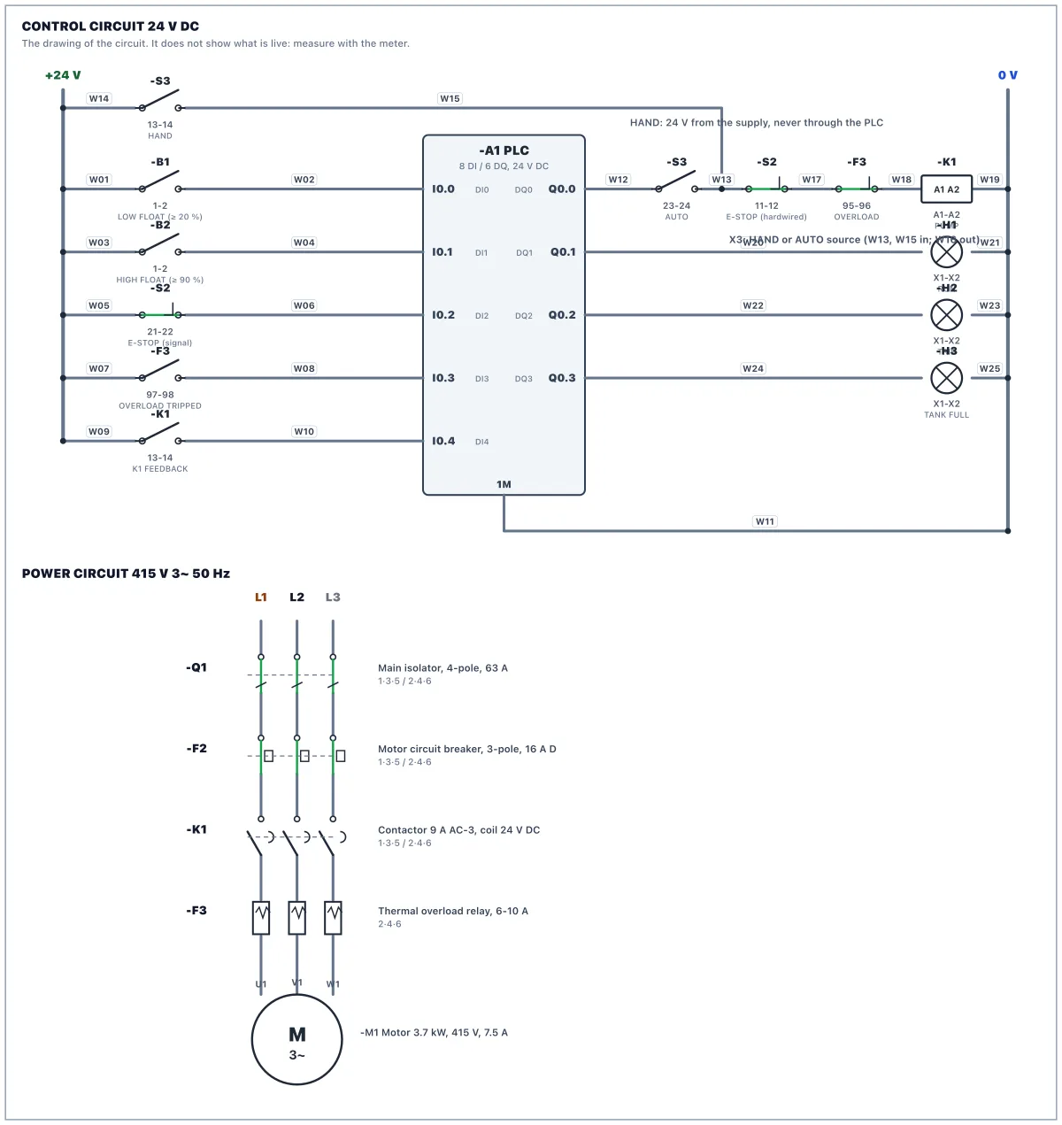
- Wire the 25 conductors of the wiring schedule. The selector S3 switches the source of K1's coil: AUTO takes it from PLC output Q0.0, HAND takes it from +24 V, OFF takes nothing. Both meet on the coil junction X3. Because the selector switches between them, the PLC output is never connected to the supply: a hand-wired link between them would feed 24 V back into the output.
- After X3 the coil circuit passes the E-STOP and the overload contact. So HAND bypasses the PLC, but it can never bypass the E-STOP or the overload.
- Read the supplied PLC program. The pump starts when the water falls below B1, fills until B2 closes, then waits.
- Restore power: tick the checklist, remove your tag and lock, switch Q1 ON, put the PLC in RUN.
- Test: OFF, AUTO through a fill cycle, HAND with the PLC stopped, the E-STOP in HAND and an overload trip. The tank starts half full and the building draws it down, so give it time to fall below B1. Then run the FAT.
Parts in the panel
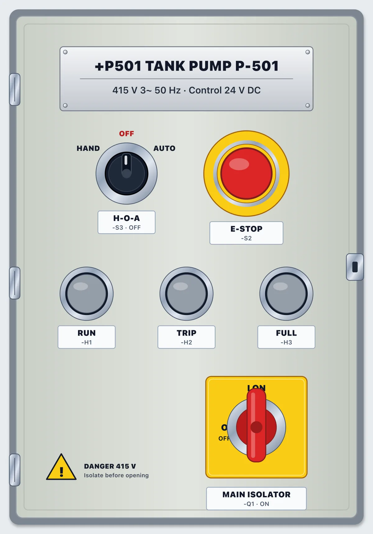
Main isolator, 4-pole, 63 A
Switches all three phases and neutral. The incoming cable lands on 1, 3, 5, 7: those terminals stay live when it is OFF.
MCB 2-pole, 6 A, C curve: control supply
Feeds the 24 V power supply with 230 V (L1 and N).
MCB 3-pole, 16 A, D curve: motor circuit
Protects the motor circuit against short circuits. The overload relay protects the motor against overload.
Contactor 3-pole, 9 A AC-3, coil 24 V DC, 1 NO aux
Switches pump P-501. Its coil gets 24 V from the selector S3, through the E-STOP and the overload contact. The 13-14 auxiliary tells the PLC it pulled in.
Thermal overload relay, 6-10 A, set 7.5 A
Trips on sustained overcurrent. 95-96 (NC) opens and 97-98 (NO) closes. Blue button: reset.
Power supply 230 V AC to 24 V DC, 5 A
Its 0 V (−) is bonded to PE at the factory, so 0 V and earth are the same potential.
PLC: compact CPU, 8 DI / 6 DQ, 24 V DC
Inputs I0.0-I0.7 are PNP: 24 V on the terminal turns the input on, with 1M at 0 V. Outputs Q0.0-Q0.5 source 24 V from 3L+.
Terminal strip X2: 24 V DC distribution
Positions 1-6 are bridged +24 V, 7-12 are bridged 0 V. Top and bottom of each position are the same point.
Terminal strip X3: coil junction, 3 terminals bridged
Where the AUTO source (from the PLC) and the HAND source (from the supply) meet. One of them is live at a time, chosen by the selector.
Terminal strip X1: motor
The motor cable from the plant lands here.
PE bar
Protective earth, bonded to the incoming supply's earth.
Selector HAND-OFF-AUTO, 2 contacts (13-14 in HAND, 23-24 in AUTO)
Chooses what feeds the contactor coil: the PLC (AUTO), the supply directly (HAND) or nothing (OFF).
Emergency stop, 2 NC, twist to release
Contact 11-12 is in the coil circuit after the selector, so it stops the pump in HAND and in AUTO; 21-22 tells the PLC.
Pilot lamp green 24 V: PUMP RUNNING
Pilot lamp amber 24 V: OVERLOAD TRIPPED
Pilot lamp white 24 V: TANK FULL
Motor 3-phase 3.7 kW, 415 V, 7.5 A, driving pump P-501
Float switch B1, low level, NO, closes at 20 %
In the overhead tank. Closed while the water is at or above 20 %; opens when it falls below.
Float switch B2, high level, NO, closes at 90 %
In the overhead tank. Closed once the water reaches 90 %.
Questions
- Is it free?
- Yes. The lab is free to use with a free account. There is nothing to buy to open this scenario.
- Do I need to install anything?
- No. It runs in your browser with a 3D panel, a circuit drawing, a meter and a PLC.
- What will I do in Panel Lab 5?
- You wire a control panel, then check your work against an acceptance test.
- How long does it take?
- Plan for one sitting. You can stop and come back.
- Do I need experience?
- No. Each work order says what to do step by step, and hints are there if you get stuck.