MOTOR CONTROL
Contactor vs Relay: Differences, Ratings and When to Use Each
What really separates a contactor from a relay: load ratings and arc handling, IEC utilisation categories AC-1, AC-3 and AC-4, interposing relays on PLC outputs, overload relays, safety relays and solid-state relays, with Tim Wilborne's teardown video.
Contactor vs relay: both are electrically operated switches, in which a coil pulls in an armature that opens or closes contacts. The difference is the job. A relay switches control signals and small loads, usually with changeover contacts. A contactor switches power loads such as motors, heaters and lighting banks, with heavy main poles built to make and break large currents and quench the arc. Under IEC rules, contactors are rated by utilisation category, such as AC-3 for motors, in IEC 60947-4-1.
Checked 5 October 2026 against IEC, BSI, Intertek and manufacturer documentation.
There is no single current where a relay becomes a contactor. RS, for example, describes contactors as the choice for loads above 15 A or 3 kW, but the real test is what the device is rated to switch. This guide explains the ratings, then shows how relays and contactors work together in a typical motor circuit.
In this video, Tim Wilborne takes a contactor apart to show what makes it work: the coil, the normally open and normally closed contacts, and how to read its voltage and horsepower ratings. It is one of the lessons in our free Electrical Control Panel Design, Building and Testing course. He uses North American ratings (horsepower, NEMA practice), so the notes below add the IEC terms used in Europe, the Gulf, Australia and most of the world.
Contactor vs relay: what is the difference?
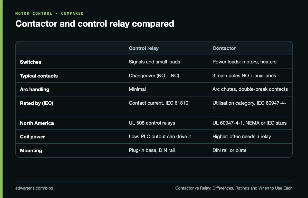
Load. A control relay's contacts are typically rated for a few amps, enough for a coil, a lamp or a PLC input. A contactor's main poles carry the full motor or heater current, and its contacts are sized to make the inrush current of a motor start and to break the running current many thousands of times.
Arc handling. Breaking an inductive load draws an arc across the opening contacts. Contactors use double-break contacts and arc chutes to stretch and cool the arc; small relays have little or none of this, which is why a relay used on a motor burns out.
Contacts. A relay usually has changeover contacts (a common, a normally open and a normally closed). A contactor has three or four normally open main poles for the load, plus auxiliary contacts, either built in or clipped on, for control circuits: a seal-in contact, a run signal back to the PLC, or an interlock.
Coil. A contactor coil draws far more power than a relay coil, especially at pick-up when an AC coil draws an inrush several times its holding power. That is why PLC outputs usually drive a relay, and the relay drives the contactor.
What do AC-1, AC-3 and AC-4 mean?
A contactor does not have one current rating. IEC 60947-4-1 defines utilisation categories, each with its own test conditions, and the manufacturer states a rating for each one. As Lovato Electric explains, the category specifies the contactor's nominal electrical performance for a specific type of load.
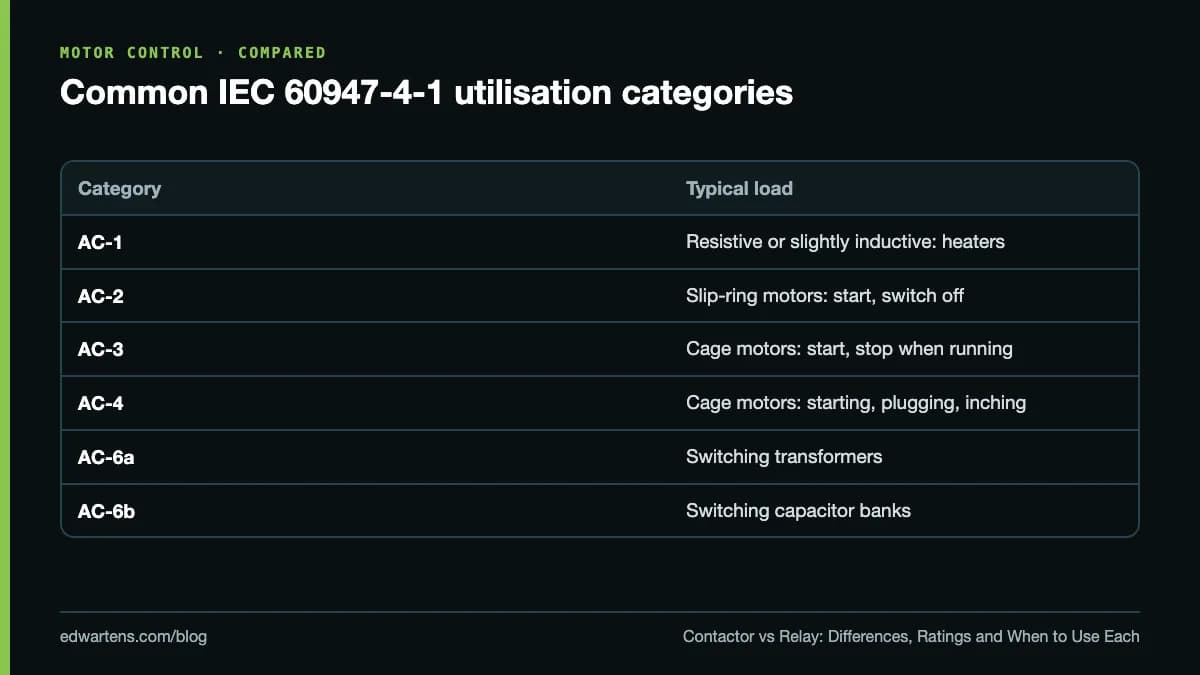
- AC-1 is the highest rating, for resistive or slightly inductive loads such as heaters.
- AC-3 is the motor rating: starting squirrel-cage motors and switching them off once running. This is the figure to use for an ordinary direct-on-line or star-delta starter.
- AC-4 covers plugging, inching and reversing, where the contactor breaks the full starting current. The AC-4 rating of the same contactor is much lower.
So a contactor listed as 40 A AC-1 and 25 A AC-3 is a 25 A motor contactor. For an 11 kW motor on a 400 V, 50 Hz supply in Germany or the UK, you choose by the AC-3 rating at 400 V in kW or amps. In North America, contactors are listed to UL 60947-4-1, which Intertek notes replaced UL 508 for new contactor and starter certifications from January 2017, and are also sold in NEMA sizes rated in horsepower at 120 V, 240 V or 480 V, 60 Hz. Our star-delta starter walkthrough shows how contactor ratings change when one motor uses three contactors.
How relays and contactors work together
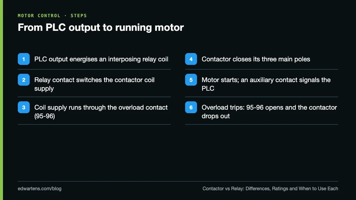
A typical motor circuit uses both, plus an overload relay.
The interposing relay
A PLC transistor or relay output has a modest current rating, set out on its datasheet, and a contactor coil may need 230 V AC, 120 V AC or a higher current than the output can supply. An interposing relay sits between them: the PLC output drives the relay's 24 V DC coil, and the relay's contact switches the contactor coil. It isolates the PLC from the coil circuit, matches the voltages, and is a cheap plug-in part to replace if it fails. Add a suppressor across the contactor coil (an RC network or a diode for DC coils) to protect the contact.
The overload relay
An overload relay is not a switch you control. It sits under the contactor, senses the motor current and, if the motor is overloaded for too long, opens its normally closed contact (95-96) in the contactor coil circuit. Set it to the motor's full-load current from the nameplate. Contactor plus overload relay is a motor starter.
The control circuit
The seal-in contact that keeps the contactor energised after the start button is released is an auxiliary contact of the contactor itself. Our start/stop ladder logic walkthrough shows the same logic in a PLC, and the inputs that feed it are covered in our guide to NPN vs PNP sensors.
How to read a contactor's markings
Before you fit or replace a contactor, check four things on its side label or datasheet:
- Coil voltage and type. For example 24 V DC, or 230 V AC 50/60 Hz. A 230 V coil on a 24 V supply will not pull in; a 24 V coil on 230 V burns out at once. North American panels often use 120 V AC coils.
- Main pole ratings. AC-3 current or power at your supply voltage, such as 400 V or 480 V, plus the AC-1 current. US-style labels also give horsepower at 120, 240 and 480 V.
- Auxiliary contacts. IEC terminal numbers tell you the function: contacts numbered 13-14 are normally open, 21-22 normally closed. Main poles are 1-2, 3-4 and 5-6, and the coil is A1-A2.
- Standards. IEC 60947-4-1, UL 60947-4-1 or both, depending on where the panel will be installed.
Safety relays, force-guided contacts and mirror contacts
In safety circuits, it matters that a welded contact can be detected. Two contact designs make that possible:
- Force-guided (mechanically linked) contacts on relays, covered by IEC 61810-3. BSI's summary of the standard explains that their construction ensures normally open and normally closed contacts can never be in the same state at once, so the relay can be used in self-monitoring safety circuits. It replaced the older EN 50205.
- Mirror contacts on contactors, defined in IEC 60947-4-1: a normally closed auxiliary contact that cannot be closed while any main contact is closed.
A safety relay (a safety monitoring module) is a different product: a device that monitors e-stops, guard switches and light curtains, checks its own wiring and drives force-guided outputs, usually controlling two contactors in series. Our guide to safety PLCs, SIL and SIS explains when a programmable safety controller replaces safety relays.
Solid-state relays vs contactors
A solid-state relay (SSR) switches with semiconductors instead of contacts. It has no contacts to wear and no arc, and it switches silently and very often, which makes it the standard choice for heaters under fast temperature control. The trade-offs: an SSR drops a voltage when on, so it gets hot and needs a heatsink; it leaks a small current when off; and it tends to fail short-circuit. It does not give the isolation of an open contact, so it is no substitute for proper isolation before maintenance. For motors, a VFD or soft starter is usually the electronic alternative; see our VFD training guide.
Choosing between a contactor and a relay
| Situation | Use |
|---|---|
| PLC output to a lamp, horn or small solenoid | Control relay, or drive directly if within rating |
| PLC output to a contactor coil | Interposing relay |
| Three-phase motor, direct-on-line | Contactor rated AC-3 plus overload relay |
| Motor with jogging or reversing duty | Contactor checked against its AC-4 rating |
| Heater bank, on/off | Contactor rated AC-1 |
| Heater under fast PID control | Solid-state relay with heatsink |
| E-stop and guard circuits | Safety relay with force-guided outputs or safety PLC |
What to learn next
Industrial Motor Control covers contactors, overload relays, starters and reversing circuits. Electrical Control Panel Design, Building and Testing, which includes this video, puts them into a panel, and our guide to electrical control panel design covers IEC 60204-1 and UL 508A. If the basics are new, start with Electrical Fundamentals for Technicians. For motors, compare starting methods in soft starter vs VFD, and choose the enclosure with our IP rating chart.
All are in the electrical courses and the electrical fundamentals path. The courses are free; an optional EDWartens Certificate of Completion, from US$2.99, is issued after the final assessment and can be checked at edwartens.com/verification. It is not a vendor certification and is not accredited. These courses teach the principles; they do not replace the electrical qualifications your country requires for work on live equipment.
Take the free course


Questions
What is the main difference between a contactor and a relay?
Both use a coil to open and close contacts, but a contactor is built and rated to switch power loads such as motors, with heavy main contacts and arc-quenching features, while a relay switches control signals and small loads. Under IEC, contactors are rated by utilisation category in IEC 60947-4-1; relays come under standards such as IEC 61810.
Can I use a relay instead of a contactor?
Only if the relay's rating covers the load's current, voltage and type, including motor inrush. Most control relays are not rated for motor starting duty, and a relay switching a motor will burn its contacts quickly. Use a contactor rated AC-3 for the motor's power and voltage.
What does AC-3 mean on a contactor?
AC-3 is the IEC 60947-4-1 utilisation category for squirrel-cage motors: starting, and switching off while running. A contactor's AC-3 rating, given in amps or kW at a stated voltage, is the figure to use when choosing one for a normal motor starter. For inching, plugging or reversing, check the AC-4 rating, which is lower.
Why use an interposing relay between a PLC and a contactor?
Because a PLC output is rated for a limited current and voltage, and a contactor coil can draw a large inrush at pick-up and may need a different supply, such as 230 V AC. The interposing relay isolates the PLC output, matches the voltages and is a cheap, plug-in part to replace if it fails.
Is an overload relay the same as a relay?
No. An overload relay is a protection device, not a switch you control. It senses motor current and, if the motor is overloaded for too long, opens an auxiliary contact (usually 95-96) in the contactor's coil circuit, which drops the contactor out. It is fitted under the contactor and set to the motor's full-load current.
When should I use a solid state relay?
Use a solid state relay (SSR) for loads switched very often, such as heaters under fast temperature control, where a mechanical contact would wear out. SSRs are silent and have no contacts to wear, but they drop a voltage and get hot, so they need a heatsink, and they can fail short-circuit. They do not give the isolation of an open contact.
Sources
- Tim Wilborne: Relays and Contactors, How Do They Work and What is the Difference
- IEC 60947-4-1:2023 Contactors and motor-starters
- Lovato Electric Academy: What is the utilization category of a contactor?
- BSI: BS EN 61810-3, relays with forcibly guided (mechanically linked) contacts
- Intertek: UL 508 and UL 60947-4-1 transition for contactors and starters
- RS: Contactor vs relay
Written by the EDWartens engineering team for general education. Product names are trademarks of their owners; mentioning them does not imply endorsement. Prices and terms of other providers were checked on the date shown and can change.

VFD Start-Up and Parameter Setup: A First Commissioning Walkthrough (Video)
4-20 mA Current Loop Explained: Wiring, Loop Power and Faults (Video)

2.3 Million Technician Openings: Deloitte-MI Study on AI and Skills
RS-485 Wiring Explained: Termination, Biasing and Daisy Chains (Video)
Structured Text Programming Tutorial: IF, CASE, Timers (Video)

Your First WinCC HMI Screen in TIA Portal, From Panel to Simulation (Video)