NPN VS PNP
NPN vs PNP Sensors: Sinking and Sourcing PLC Inputs Explained
PNP sources current, NPN sinks it, and the PLC input has to be the opposite. The wiring for both, the naming trap between vendors, 2-wire leakage and a fault-finding checklist.
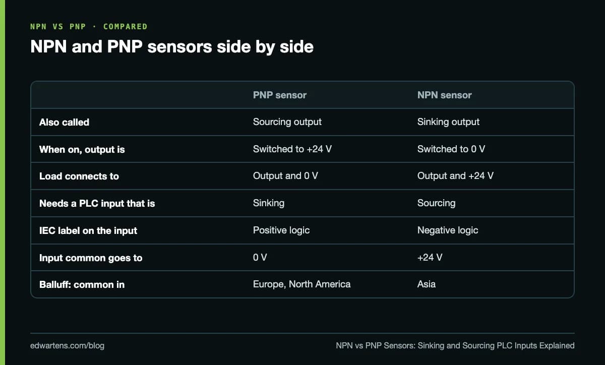
A PNP sensor switches the positive supply (+24 V) onto its output when it detects a target, so it sources current into the load. An NPN sensor switches its output to 0 V, so it sinks current from the load. A PNP sensor must go to a sinking PLC input (common on 0 V) and an NPN sensor to a sourcing input (common on +24 V). Neither is better; match the sensor to the input.
Checked 5 October 2026 against AutomationDirect, Balluff, Pepperl+Fuchs and Texas Instruments documentation.
What do sinking and sourcing actually mean?
AutomationDirect's definitions are the clearest in print. A sinking circuit provides a path to the supply common (the negative side). A sourcing circuit provides a path to the supply source (the positive side). Current, in these definitions, is conventional current flowing from + to -.
Every DC input or output circuit has to be paired with its opposite. A sourcing device pushes current out; a sinking device takes it in and returns it to 0 V. Put two sourcing devices together and there is nowhere for the current to go; put two sinking devices together and there is nothing to supply it. Either way the circuit never turns on, even though every wire looks right.
Two consequences follow:
- The terms only apply to DC. AC has no fixed polarity, so an AC input is neither sinking nor sourcing.
- A sensor and its input are always opposites. PNP (sourcing) sensor, sinking input. NPN (sinking) sensor, sourcing input.
How a PNP sensor is wired to a PLC
Most 3-wire DC sensors follow IEC 60947-5-2 wire colours. A Pepperl+Fuchs inductive sensor datasheet, for example, lists brown (pin 1) as L+, blue (pin 3) as L- and black (pin 4) as the output.
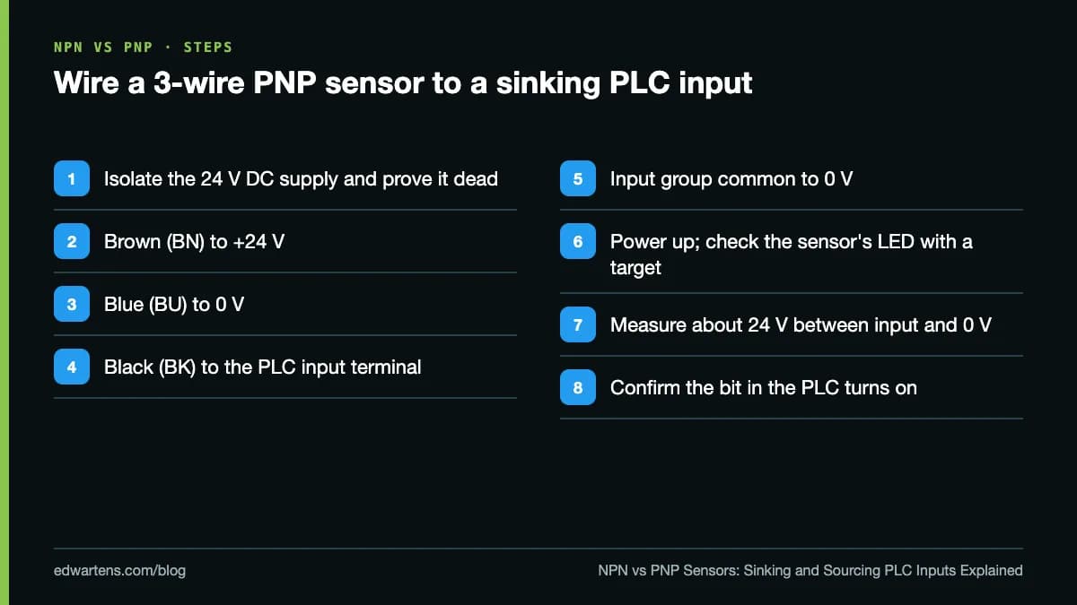
The sensor takes its own power from brown and blue. When a target arrives, its output transistor connects black to +24 V. Current flows from black into the PLC input, through the input's optocoupler, out of the input group's common terminal and back to 0 V. The PLC sees about 24 V minus the sensor's voltage drop at its input, and the bit turns on. The same datasheet gives that drop as up to 1.5 V, so the input still sees well over 20 V.
How an NPN sensor is wired to a PLC
Brown and blue go to +24 V and 0 V exactly as before. The difference is on the input side: the input group's common now goes to +24 V. When the sensor switches on, it connects black to 0 V. Current flows from +24 V into the common terminal, through the input circuit, out of the input terminal and down the black wire through the sensor to 0 V.
Notice that with an NPN sensor the PLC input terminal is at 0 V when the sensor is on. If you measure between the input and 0 V, you see about 0 V when the input is on and about 24 V when it is off, which confuses people who are used to PNP. Measure between the input and its common instead and you see 24 V whenever current flows.
The naming trap: sinking input or positive logic?
Here is where most of the confusion comes from. Different vendors describe the same circuit in opposite words.
- Describing the input card. A "sinking input" sinks current, so it suits a PNP sensor. American documentation, including AutomationDirect's, tends to use this wording.
- Describing the logic. IEC-style documentation calls the same circuit positive logic, because a positive voltage on the terminal means on. AutomationDirect prints both labels side by side: sinking input (IEC: positive logic), sourcing input (IEC: negative logic).
- Describing the sensor. Some manuals label an input "PNP" or "source" because of the sensor it expects, not the current direction at the terminal.
So never trust the word alone. Look at the wiring diagram in the manual and ask one question: where does the common go? Common to 0 V means the input wants a PNP (sourcing) sensor. Common to +24 V means it wants an NPN (sinking) sensor.
Sink/source inputs: one card, either sensor
Many PLCs and drives have inputs that work either way. AutomationDirect describes sink/source inputs as circuits that let current flow in either direction: the common goes to one polarity and the input point to the other, through the field device. Two rules come with that flexibility:
- Every point on a shared common must be wired the same way. If the group's common is on 0 V, every sensor on that group must be PNP.
- Never put AC on a DC sink/source input.
Drives work the same way. AutomationDirect's GS20 manual lists seven sinking/sourcing DC inputs on the drive and explains that a sinking input turns on when you apply voltage, so it needs a sourcing device such as a PLC sourcing output or a switch to +24 V. Many drives select the mode with a switch or a parameter, so check it before you wire a PLC output to a drive.
Which should you choose?
On a new design, match what the plant already uses, so maintenance only stocks one type. Balluff's sensor primer notes that PNP outputs are common in Europe and North America and NPN outputs are common in Asia, which is why a machine shipped from one region can arrive with the "wrong" sensors for another.
If you have a free choice, many engineers pick PNP sensors with sinking inputs where 0 V is earthed. The reason is the most common wiring fault: a damaged cable shorting to earth. With PNP, a signal wire shorted to 0 V reads as off. With NPN, the same short pulls the input to 0 V and reads as on, which can look like a part that is not there. That is a design preference, not a safety function; anything protecting people belongs on a safety-rated circuit.
2-wire sensors and leakage current
A 2-wire DC sensor has no separate supply wires. It powers itself from a small current that flows through the PLC input even when the sensor is off. If that off-state current is larger than the input will tolerate as "off", the input can flicker or stay on.
Compare two numbers before you fit one: the sensor's off-state (residual) current from its datasheet, and the off-state current the input card accepts. IEC 61131-2 defines three types of 24 V digital input (Type 1, 2 and 3) with different current and voltage thresholds. Texas Instruments' design notes describe Type 1 and Type 3 inputs as drawing as close to 2 mA as possible in the on state. By contrast, the 3-wire Pepperl+Fuchs sensor above lists an off-state current of 10 µA or less, which is why 3-wire sensors rarely have this problem.
Fault-finding a sensor that will not turn the input on
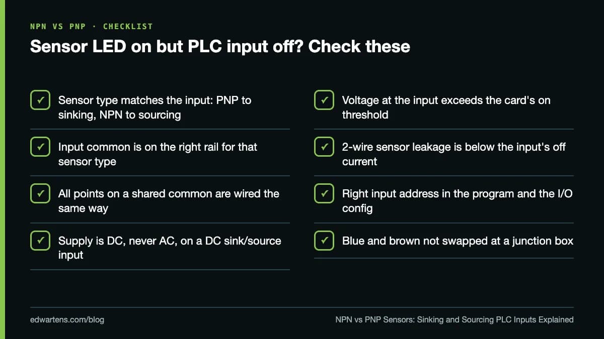
Work from the sensor towards the PLC with a multimeter:
- Supply at the sensor. Brown to blue should read about 24 V.
- Sensor output. For PNP, black to blue should jump to about 24 V when the target arrives. For NPN, black to brown should jump to about 24 V.
- At the input terminal. Measure between the input and its common. About 24 V there means current can flow, so if the bit is still off, look at the card, the address or the configuration.
- If the sensor switches but the input reads nothing, the sensor type and input type do not match, or the common is on the wrong rail.
Learn it hands-on, free
Our free Instrumentation for PLC Engineers course has a module on switches, proximity sensors and encoders that covers sinking and sourcing wiring with animated videos from Instrumentation Academy. The Electrical Control Panel Design, Building and Testing course includes a full lesson on sinking and sourcing PLC inputs with PNP and NPN sensors by Tim Wilborne. If the electrical basics are new, start with Electrical Fundamentals for Technicians, and see the Industrial Instrumentation and Process Control course for proximity, photoelectric and Hall-effect sensors.
These sit in the electrical courses and PLC courses. Wiring questions like this one come up in almost every interview; our PLC interview questions and answers has more. Every course is free, with an optional EDWartens Certificate of Completion from US$2.99 after a final assessment, verifiable at edwartens.com/verification. It is not a vendor certification and is not accredited.
Take the free course

Instrumentation · Intermediate · Free
Instrumentation for PLC Engineers

Electrical · Beginner · Free
Electrical Control Panel Design, Building and Testing

Instrumentation · Beginner · Free
Industrial Instrumentation and Process Control

Electrical · Beginner · Free
Electrical Fundamentals for Technicians: Volts to Multimeter to Drawings
Questions
Is PNP sinking or sourcing?
A PNP sensor is a sourcing device: when it switches on, it connects its output to the positive supply and pushes current into the load. It therefore needs a sinking PLC input, one whose common is connected to 0 V. An NPN sensor is the opposite: a sinking output that needs a sourcing input with its common on +24 V.
Can I connect an NPN sensor to a PNP (sinking) PLC input?
Not directly; the input will never see current flow the right way. Your options are to replace the sensor with a PNP version, move it to an input group wired as sourcing (common on +24 V) if the card is sink/source and that group has no PNP devices on it, or add an interface relay between the sensor and the input.
Which is better, NPN or PNP?
Neither is better electrically; the rule is to match the input card. In practice PNP is the default in Europe and North America and NPN is more common on equipment from Asia. Many engineers prefer PNP with sinking inputs on systems where 0 V is earthed, because a signal wire shorted to earth then reads as off rather than on.
What do the brown, blue and black wires on a sensor mean?
On 3-wire DC sensors that follow IEC 60947-5-2, brown is the positive supply (L+), blue is 0 V (L-) and black is the switched output. On an M12 or M8 connector those are usually pins 1, 3 and 4. Check the datasheet, because 4-wire sensors add a white wire for a second output.
Do sinking and sourcing apply to AC inputs?
No. The terms describe the direction of DC current, so they only apply to DC inputs and outputs. AutomationDirect's documentation also warns never to put an AC supply on a DC sink/source input.
Sources
- AutomationDirect: Sinking and Sourcing Concepts (catalogue appendix)
- AutomationDirect: GS20 AC drive manual, Appendix D (sinking/sourcing basics)
- Balluff: Fundamentals of Automation, NPN vs PNP
- Pepperl+Fuchs: NBB1,5-F79-E2-Y70118840 inductive sensor datasheet
- Texas Instruments: How to simplify isolated 24 V PLC digital input module designs (SLLA370)
- Texas Instruments: ISO1211/ISO1212 isolated digital input receiver datasheet
Written by the EDWartens engineering team for general education. Product names are trademarks of their owners; mentioning them does not imply endorsement. Prices and terms of other providers were checked on the date shown and can change.