4-20 MA VIDEO
4-20 mA Current Loop Explained: Wiring, Loop Power and Faults (Video)
How a 4-20 mA loop works, with Precision Digital's free webinar: why the zero is 4 mA, 2-wire and 4-wire transmitters, how much voltage a loop needs, the NAMUR NE 43 fault currents and how to check a loop.
A 4-20 mA current loop sends a measurement as a DC current: 4 mA means 0% of the instrument's range and 20 mA means 100%. Because the current is the same everywhere in a series loop, the signal survives long cables and electrical noise, and because the zero is "live" at 4 mA, a broken wire (about 0 mA) can never be mistaken for a real zero reading.
Checked 5 October 2026 against NI, Fluke, NAMUR and ISA documentation.
The 4-20 mA current loop is still the most common way to wire a process transmitter to a PLC or DCS, from water works in the UK to refineries in the Gulf. ISA's analogue signal standard, ANSI/ISA-50.00.01-1975 (R2012), Compatibility of Analog Signals for Electronic Industrial Process Instruments, is where the range comes from. This walkthrough explains the loop with a free webinar, then adds the parts a technician needs on site: wiring types, the voltage budget, fault currents and a loop check.
This recorded webinar from Precision Digital is an introductory class for people who handle process signals but are not electrical engineers. It covers the history of the 4-20 mA loop, how it works, its pros and cons, and how to choose the right devices for an installation. It runs for just under an hour, and it is one of the lessons in our free Instrument Calibration, Loop Checks and Commissioning course. Watch it in sections and use the notes below alongside.
How does a 4-20 mA current loop work?
A loop has four parts, all in series, as NI's white paper on the 4 to 20 mA loop describes them: a DC power supply, the transmitter, the receiver (a PLC or DCS analogue input, an indicator or a recorder), and the wire that joins them. The transmitter does not send a voltage. It acts as a regulated current sink, letting through exactly the current that represents its measurement, and the receiver measures that current, usually as the voltage across a precision resistor.
Why a current? In a series circuit the current is the same at every point, so cable resistance does not change the reading as long as the supply has enough voltage to push the current through. A voltage signal, by contrast, loses accuracy with every ohm of cable. Current loops are also less sensitive to induced noise, which is why the method has outlived decades of fieldbus and Ethernet alternatives.
Converting current to a reading
The relationship is linear:
value = lower range + (current - 4) / 16 x span
Take a pressure transmitter ranged 0 to 10 bar. At 12 mA: (12 - 4) / 16 = 0.5, so the reading is 5 bar. At 6.4 mA: 2.4 / 16 = 0.15, so 1.5 bar. In a Siemens S7-1200 or S7-1500, the analogue input converts 4 to 20 mA into raw counts of 0 to 27,648, and the program scales those counts back to engineering units. Our free 4-20 mA Scaling Calculator does both sums, and the guide to our free engineering calculators shows worked examples.
Why 4-20 mA and not 0-20 mA?
Two reasons. First, the live zero: Fluke's explainer puts it simply, the 4 mA lets a system tell a valid zero from a fault such as a broken wire or power loss. Second, power: a 2-wire transmitter takes its operating power from the loop, and 4 mA is enough to run its electronics even when the measurement is at zero. A 0-20 mA loop cannot do either.
2-wire, 3-wire and 4-wire transmitters
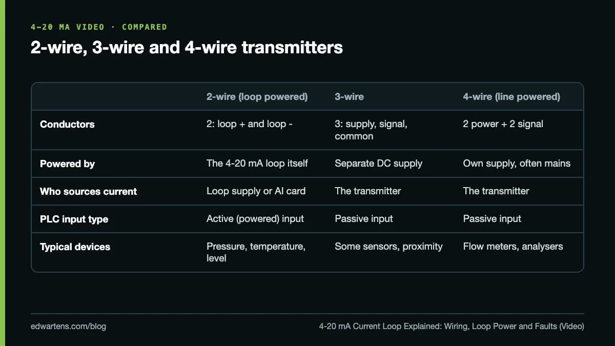
The wiring type decides how you connect to the PLC, and getting it wrong is the most common commissioning fault on analogue loops.
- 2-wire (loop-powered). The transmitter has no power of its own. Something in the loop must supply 24 V DC: either an active (powered) analogue input channel, or a separate loop supply with a passive input. Most pressure, temperature and level transmitters are 2-wire.
- 4-wire (line-powered). The transmitter has a separate power supply, often 230 V or 120 V AC mains, and its output drives the current. Connect it to a passive input. Connecting an active output to an active input puts two sources in one loop, and the reading will be wrong or the input damaged.
- 3-wire. A common supply terminal is shared between power and signal. Check the manual: the shared negative must match the input card's common.
This is the analogue cousin of the sinking and sourcing problem on digital inputs, covered in our guide to NPN vs PNP sensors. For more on wiring types, Instrumentation Tools has a five-minute video, Different Types of 4-20 mA Transmitter Wiring, which is also in our free Industrial Instrumentation and Process Control course.
How much voltage does a 4-20 mA loop need?
Every device in the loop drops some voltage, and the supply must cover all of them at 20 mA, the worst case. This is the loop voltage budget:
supply voltage = transmitter minimum voltage + (input resistance + cable resistance + other loads) x 0.020 A
The transmitter's minimum voltage, sometimes called lift-off voltage, is on its datasheet. NI's white paper gives a worked case: a transducer needing 12 V, a 249 ohm shunt resistor and 2,000 ft of 24-gauge copper add up to about 21.2 V, so a 24 V supply is needed.
Worked example: maximum cable length
| Item | Value |
|---|---|
| Loop supply | 24 V DC |
| Transmitter minimum voltage | 12 V (from its datasheet) |
| PLC input resistance | 250 ohms, so 5 V at 20 mA |
| Voltage left for the cable | 24 - 12 - 5 = 7 V |
| Maximum cable resistance | 7 V / 0.020 A = 350 ohms |
| 1 mm² solid copper (IEC 60228 max 18.1 ohms/km), two conductors | about 36 ohms per km of route |
| Maximum route length | about 9.7 km, before margins |
Real loops rarely get near that limit, but the budget catches other problems. Add a 250 ohm HART resistor, a loop-powered display and an intrinsic safety barrier, and a loop that worked on the bench can stop reaching 20 mA in the field. That symptom, a reading that tops out below full scale, is almost always an undervoltage loop. Always budget at the lowest voltage the supply can sag to, and leave margin.
What do 3.6 mA and 21 mA mean? NAMUR NE 43
A modern smart transmitter can diagnose itself: a broken sensor, a failed electronics check. The question is how to tell the PLC. The answer most process plants use is NAMUR NE 43, a recommendation from NAMUR, the German-founded association of process automation users. Its current recommendations list dates the latest edition 26 July 2021.
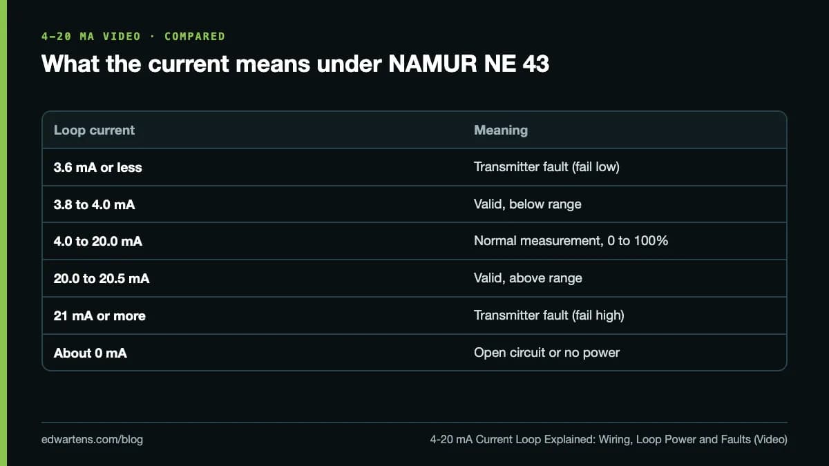
NE 43 keeps valid measurements between 3.8 and 20.5 mA, allowing a little under-range and over-range, and reserves 3.6 mA or less and 21 mA or more for failure signals. The PLC or DCS then raises a transmitter fault alarm instead of acting on a wrong value. Whether the transmitter fails low or high is configurable, and the right choice depends on the process. On a high-level trip, for example, failing high puts the plant into its safe state. Decide it with the process and safety engineers, and set the PLC's alarm limits to match.
How to check and troubleshoot a 4-20 mA loop
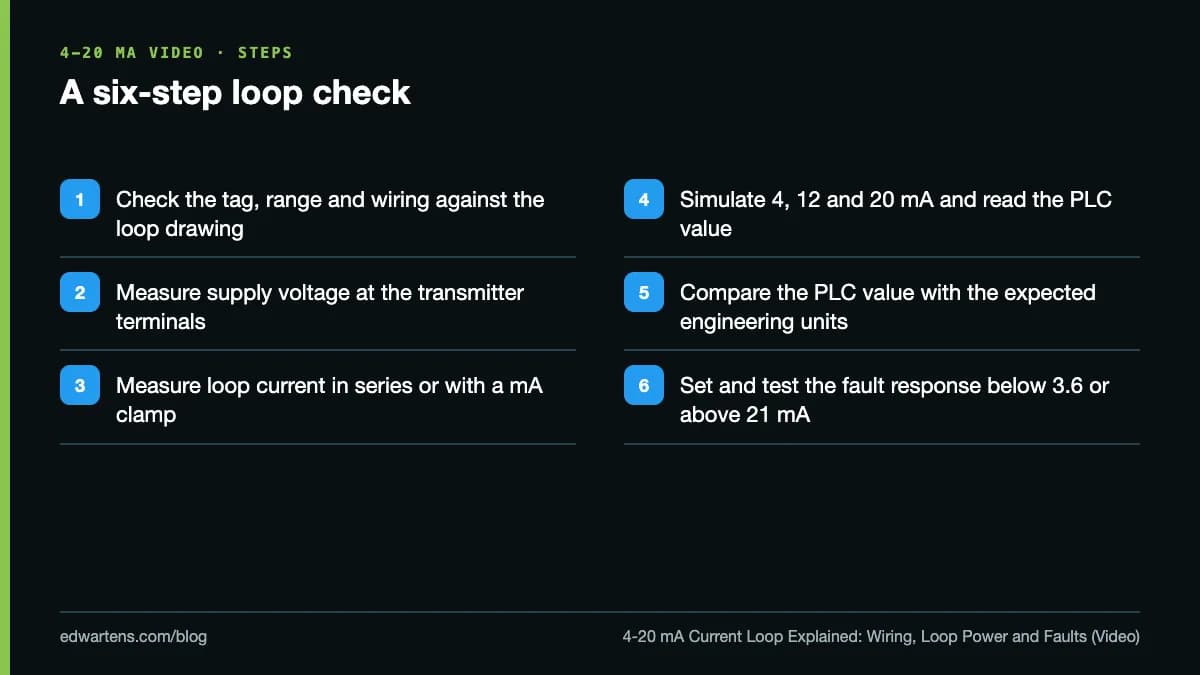
A few habits save a lot of time:
- Measure current without opening the loop if you can. A milliamp clamp meter reads loop current around the wire. Some transmitters have test terminals across a diode, where a milliammeter can read the current without breaking the circuit. Otherwise you must open the loop and connect the meter in series. Never put a meter set to current across a powered supply: it is a short circuit, and it is how meter fuses get blown.
- Put the loop in manual first. Opening a loop sends the reading to zero or to a fault value, and a controller in automatic will react.
- Simulate, then compare. Use a loop calibrator to source or simulate 4, 12 and 20 mA, then check that the PLC shows 0%, 50% and 100% in engineering units. A wrong middle value with correct ends points to a scaling error; a wrong value everywhere points to wiring or the input configuration.
- Record it. A loop check sheet with the as-found and as-left values is what a commissioning manager wants to see. Our guide to becoming a commissioning engineer explains where loop checks fit in a project.
Common faults
| Symptom | Likely cause |
|---|---|
| 0 mA | Open circuit, blown fuse, no loop power |
| Stuck at 3.6 mA or below | Transmitter fault signal (NE 43) |
| Stuck at 21 mA or above | Transmitter fault signal, or shorted loop |
| Never reaches 20 mA | Loop voltage too low for the load |
| Reading noisy or jumping | Shield grounded at both ends, poor terminal |
| Wrong value at all points | Scaling or input range set wrongly |
Before you trace a loop, check the tag and range on the P&ID and the loop drawing. Our guide on how to read a P&ID explains how LT-101 and its loop number lead you to the right drawings.
What to learn next
Start with Instrument Calibration, Loop Checks and Commissioning, which contains this webinar. Instrumentation for PLC Engineers follows one measurement from the transmitter into the PLC, and Siemens TIA Portal PID Compact and Analog Processing covers scaling and control in code. For the instruments themselves, read our process instrumentation basics. Networks that replace analogue wiring are next: see our guide to RS-485 wiring and, for Ethernet networks, PROFINET vs EtherNet/IP.
All of these sit in the instrumentation and process control courses. Every course is free. If you want proof of study, an optional EDWartens Certificate of Completion, from US$2.99, is issued after you pass the final assessment and can be checked at edwartens.com/verification. It is not a vendor certification and is not accredited.
Take the free course

Instrumentation · Beginner · Free
Instrument Calibration, Loop Checks and Commissioning

Instrumentation · Beginner · Free
Industrial Instrumentation and Process Control

Instrumentation · Intermediate · Free
Instrumentation for PLC Engineers

Process control · Intermediate · Free
Siemens TIA Portal PID Compact and Analog Processing
Questions
Why is 4 mA used instead of 0 mA?
Because a live zero lets the receiver tell a real 0% reading from a broken wire or a dead transmitter. At 0% the loop still carries 4 mA, so a current near 0 mA can only mean a fault. The 4 mA also gives a 2-wire transmitter enough current to power its own electronics.
What is the difference between a 2-wire and a 4-wire transmitter?
A 2-wire transmitter is powered by the loop itself: the same two wires carry its power and its 4-20 mA signal, so it needs a powered (active) input or a separate loop supply. A 4-wire transmitter has its own power supply and drives the current itself, so it connects to a passive input.
How long can a 4-20 mA cable run be?
As long as the loop voltage budget allows. Subtract the transmitter's minimum voltage and the voltage across the input resistor at 20 mA from the supply; what is left, divided by 0.02 A, is the most cable resistance the loop can have. With 24 V, a 12 V transmitter and a 250 ohm input, that is 350 ohms, which is several kilometres of 1 mm² copper.
How do you measure 4-20 mA without breaking the loop?
Use a clamp meter made for milliamp loops, or, if the transmitter has test terminals, connect a milliammeter across them. Otherwise you must open the loop and put the meter in series, which interrupts the signal, so tell the operator and put the control loop in manual first.
What does 3.6 mA or 21 mA mean on a transmitter?
Under the NAMUR NE 43 recommendation, a current of 3.6 mA or less, or 21 mA or more, means the transmitter has detected a fault in itself or its sensor. Valid readings stay between 3.8 and 20.5 mA. Many transmitters let you choose whether a fault drives the output low or high.
Can I convert 4-20 mA to 0-10 V with a resistor?
Not exactly. A resistor turns current into voltage, but 4 mA never becomes 0 V: a 250 ohm resistor gives 1 to 5 V and a 500 ohm resistor gives 2 to 10 V. For a true 0 to 10 V signal you need a signal converter, and the extra resistance must still fit the loop voltage budget.
Sources
- Precision Digital: The Fundamentals of 4-20 mA Current Loops (webinar)
- NI: Fundamentals, system design and setup for the 4 to 20 mA current loop
- Fluke: What is a 4-20 mA current loop?
- NAMUR: current recommendations and worksheets (NE 43, edition 2021-07-26)
- ISA: ANSI/ISA-50.00.01-1975 (R2012) Compatibility of Analog Signals
Written by the EDWartens engineering team for general education. Product names are trademarks of their owners; mentioning them does not imply endorsement. Prices and terms of other providers were checked on the date shown and can change.

PID Tuning Explained With a Simulator (Video)
Contactor vs Relay: Differences, Ratings and When to Use Each
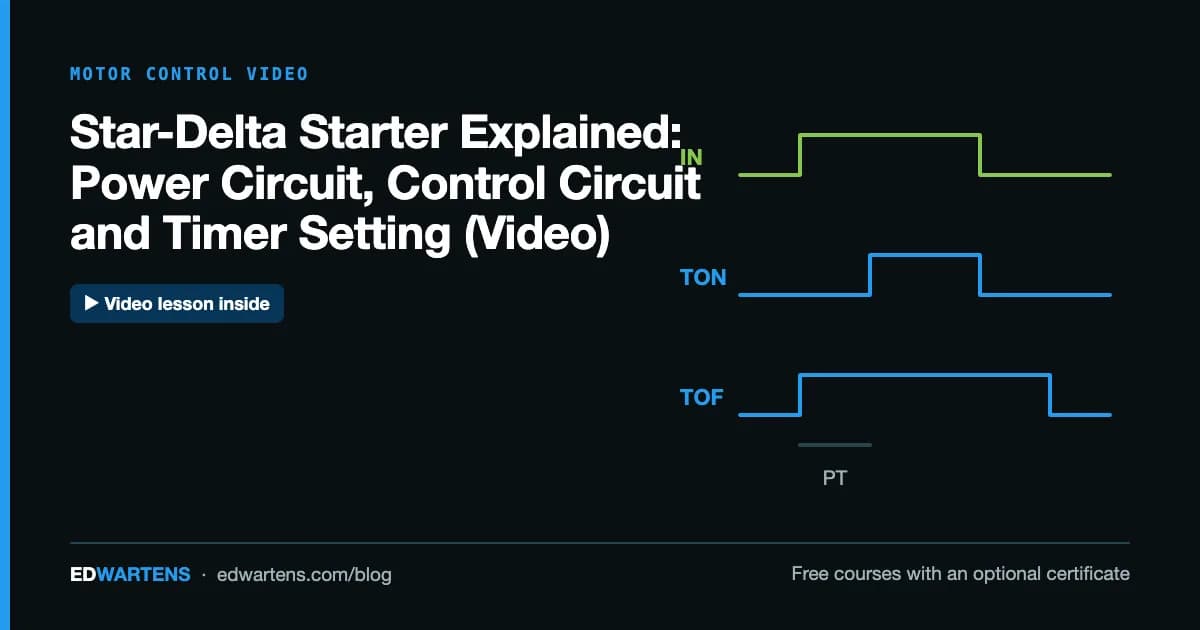
Star-Delta Starter Explained: Power Circuit, Control Circuit and Timer Setting (Video)
Structured Text Programming Tutorial: IF, CASE, Timers (Video)

Your First WinCC HMI Screen in TIA Portal, From Panel to Simulation (Video)

Your First S7-1200 Program in TIA Portal and PLCSIM (Video)