RS-485 VIDEO
RS-485 Wiring Explained: Termination, Biasing and Daisy Chains (Video)
How to wire an RS-485 bus that works first time, with RealPars' short video: daisy-chain topology, termination at both ends, biasing at one point, the A/B naming problem, cable length and a checklist for a silent Modbus RTU bus.
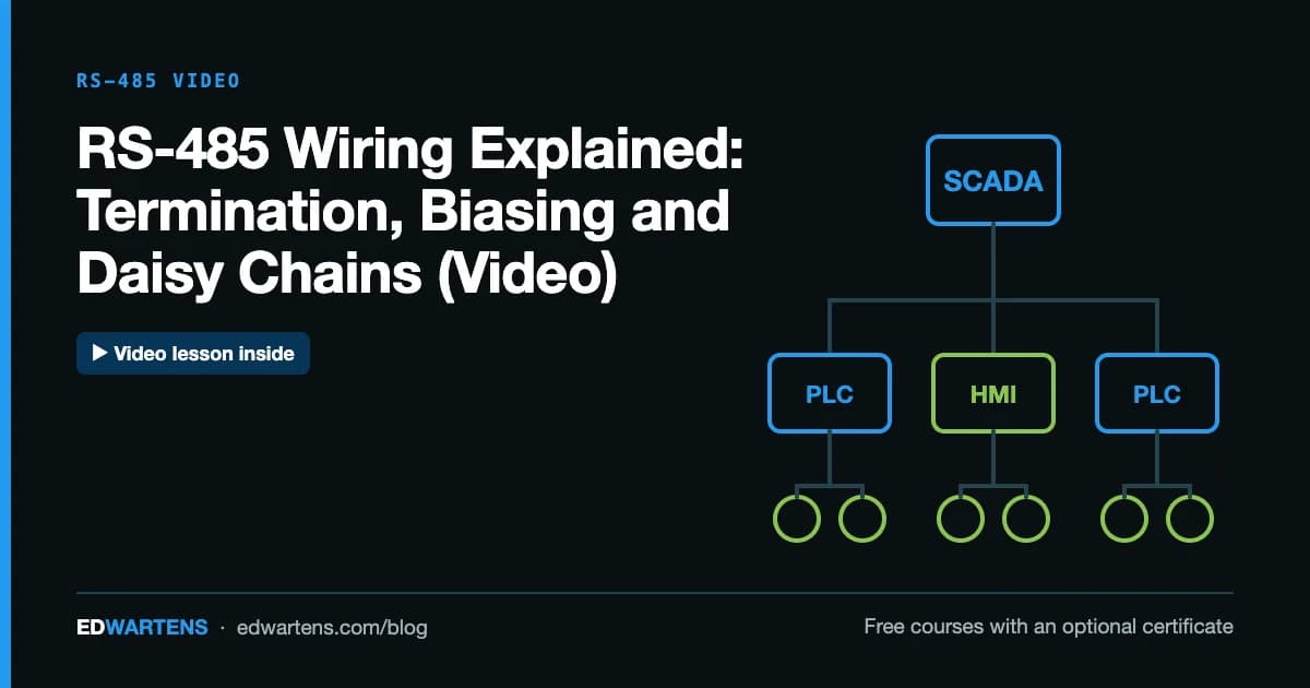
RS-485 wiring (often searched as RS485 wiring) means one shielded twisted pair, plus a common conductor, run as a single trunk from device to device (a daisy chain), with a 120 ohm termination resistor at each of the two ends and biasing resistors at one point only. Every device connects its D1 (often labelled B) to the same wire and its D0 (often A) to the other. Get those four things right and most Modbus RTU networks work first time.
Checked 5 October 2026 against the Texas Instruments RS-485 design guide and the Modbus serial line specification.
RS-485 is the physical layer under Modbus RTU, many drive and meter networks, and plenty of building automation. It is a wiring standard, not a protocol: it defines the electrical signals, and protocols such as Modbus define the messages. This guide covers the RS-485 wiring itself. For the messages, see our Modbus tutorial.
In this six-minute video, RealPars explains what RS-485 is and why industry uses it: a serial standard like RS-232, but one that can run a bus connecting many devices rather than a single device-to-device link, over far longer cables. It is one of the lessons in our free Industrial Communication course. The notes below add the wiring detail you need on site.
How does RS-485 work?
RS-485 uses differential signalling. The driver puts opposite voltages on the two wires of a twisted pair, and the receiver looks only at the difference between them. The Texas Instruments RS-485 design guide gives the numbers: a standard driver produces at least 1.5 V across a 54 ohm load, and a receiver detects a difference as small as 200 mV. Noise picked up along the cable affects both wires equally, so it cancels out at the receiver. That is how RS-485 reaches about 1,200 m (4,000 ft) at 100 kbit/s, and up to 10 Mbit/s over short distances.
Most industrial RS-485 is 2-wire, half duplex: one pair carries data in both directions, and devices take turns to talk. Modbus RTU works that way, with one master polling each slave in turn. 4-wire, full duplex RS-485 uses a separate pair for each direction and appears on some older equipment; the Modbus specification describes both.

RS485 wiring step by step: how to wire the bus

Topology: daisy chain, not star
An RS-485 bus is one trunk cable with both ends terminated. Each device connects to the trunk directly, cable in and cable out, or by a short drop. The Modbus specification limits drops to 20 m, and a star, where several long cables leave one point, creates reflections that no terminator can fix. If the plant layout wants a star, use a repeater or hub designed for it.
Cable
Use twisted-pair cable built for RS-485, with a characteristic impedance of about 120 ohms. TI's guide shows 22 to 24 AWG twisted pair. Shielded cable is usual in plants. You also need a third conductor for the common (0 V) reference: RS-485 receivers tolerate only a limited voltage difference between devices, and the data pair alone does not hold them together. The Modbus specification connects the common to protective earth at one point only for the whole bus, generally at the master. Follow the device manuals for the shield.
Where does the RS-485 termination resistor go?
At the two physical ends of the trunk, and nowhere else. A signal travelling down a cable is partly reflected wherever the impedance changes, and an open cable end reflects almost all of it. A resistor matching the cable impedance absorbs the signal instead.
- Value. TI's guide terminates a 120 ohm cable with a 120 ohm resistor at each end. The Modbus specification allows 150 ohms, or a 120 ohm resistor in series with a 1 nF capacitor where the line is biased.
- Never more than two. The Modbus specification forbids more than two terminators on one pair, and none on a drop cable. Many drives and meters have a built-in terminator switch; make sure only the two end devices have it on.
What are RS-485 biasing resistors?
When no device is transmitting, nothing drives the pair, and the receivers can read noise as data. Biasing (also called polarisation or fail-safe biasing) holds the idle bus in a defined state with a pull-up resistor on one wire and a pull-down on the other.
The Modbus over Serial Line specification, V1.02, free from the Modbus Organization's specifications page, is precise: if any device needs it, fit one pull-up to 5 V on D1 and one pull-down to common on D0, each between 450 and 650 ohms, at one location for the whole bus, generally the master. Other devices must not add their own. Schneider Electric's support FAQ on RS-485 termination and biasing says the same: only one device on the bus should provide biasing, so devices with built-in bias resistors need a switch to disable them. Biasing loads the bus, so the Modbus specification reduces the allowed device count by four when it is fitted.
Many modern transceivers have built-in fail-safe circuits, but TI notes that their noise margin is small, so in a noisy plant external biasing is still the safer choice.
A and B: the naming problem
The two data wires are labelled differently by different manufacturers: A and B, A and B swapped, plus and minus, D+ and D-, or TxD/RxD. One maker's A can be another maker's B. The Modbus specification avoids the letters altogether and names the wires D0 and D1, with D1 positive when the line is idle, and asks every device's documentation to use those names. Its own table maps D0 to A/A' and D1 to B/B'.
On site, the rule is simple: check each manual, connect like to like, and if one device stays silent while the rest answer, swap its two data wires. A reversed pair does no damage.
How many devices and how far?
| Limit | Value | Source |
|---|---|---|
| Unit loads per bus | 32 | RS-485 standard, per TI |
| Devices without a repeater (Modbus) | 32 | Modbus serial line spec |
| Length at 100 kbit/s or less | About 1,200 m | TI design guide |
| Length at 9,600 baud, AWG26 or thicker | 1,000 m | Modbus serial line spec |
| Drop length from the trunk | 20 m maximum | Modbus serial line spec |
Transceivers rated at 1/8 of a unit load allow more devices: TI's guide calculates up to 96 on a biased bus. Beyond the limits, a repeater starts a new segment.
Shield, grounding and noise
Shielded cable helps only if the shield is handled consistently. The common approach in plants is to bond the shield to earth at one end, usually the master, and to carry it through at every device without connecting it to the device's signal common. Some manufacturers specify earthing at both ends with equipotential bonding; follow the manuals of the devices on your bus, and do not mix approaches on one cable. Keep RS-485 cables away from motor cables and VFD outputs, and cross power cables at right angles. A noisy bus usually shows up as intermittent CRC or timeout errors, not a total failure.
Troubleshooting a silent RS-485 bus

Work from the bottom of the stack up. Check the wiring and termination, then the serial settings (every device must use the same baud rate, parity and stop bits), then the addresses, then the message itself. A cheap USB-to-RS-485 adapter and a free Modbus master tool on a laptop let you poll one device at a time and split the problem in half. Our Modbus TCP walkthrough uses the same register model, so once a serial device answers, the next steps are identical.
A common real-world case is a group of VFDs on one bus. Set each drive's address and serial parameters during commissioning, as in our VFD start-up walkthrough, enable the terminator only on the last drive, and bias once at the PLC.
Where RS-485 goes next
Plants increasingly bridge serial devices to Ethernet with a gateway, then read them from a PC or edge device. Our Node-RED PLC dashboard walkthrough shows the data side of that. If you are choosing an Ethernet network for new equipment, read PROFINET vs EtherNet/IP. For analogue signals that RS-485 often replaces, see our guide to the 4-20 mA current loop.
To go further, take Industrial Communication for serial, fieldbus and Ethernet networks, Variable Frequency Drives for drives on Modbus, and Node-RED for Industrial IoT to collect the data. They are in the networks courses. The courses are free; an optional EDWartens Certificate of Completion, from US$2.99, is issued after the final assessment and is verifiable at edwartens.com/verification. It is not a vendor certification and is not accredited.
Take the free course


Questions
Do I need a termination resistor on RS-485?
On a long or fast bus, yes: a terminator at each end of the trunk stops signal reflections. The Modbus serial line specification requires a line termination near each of the two ends of the bus and never on a drop cable. On a very short, slow bench link, a missing terminator often goes unnoticed, which is why it fails later in the field.
What value termination resistor for RS-485?
Match the cable's characteristic impedance, which for RS-485 twisted pair is usually 120 ohms, so 120 ohm resistors at both ends is the common choice. The Modbus specification allows a 150 ohm resistor, or a 120 ohm resistor in series with a 1 nF capacitor where the line is biased.
Which is A and which is B on RS-485?
It depends on the manufacturer, which is why swapped pairs are the most common RS-485 fault. The Modbus specification avoids the letters and names the wires D0 (A/A') and D1 (B/B'), with D1 positive in the idle state. If a device does not answer, swapping its two data wires is a safe test.
How many devices can be on one RS-485 bus?
The standard allows 32 unit loads, so 32 full-load devices, and the Modbus specification authorises 32 devices without a repeater. Transceivers rated at a fraction of a unit load allow more devices, and biasing resistors use up some of the load budget. Beyond that, add a repeater.
What is the maximum RS-485 cable length?
About 1,200 m (4,000 ft) at 100 kbit/s or less, according to Texas Instruments' design guide; higher data rates need shorter cables. The Modbus specification gives 1,000 m at 9,600 baud with AWG26 or thicker cable.
What is the difference between RS-485 and RS-232?
RS-232 is single-ended and point to point, for one device over a few metres. RS-485 is differential, which rejects noise, and is a multidrop bus: up to 32 devices on one twisted pair over hundreds of metres. That is why industrial serial networks such as Modbus RTU run on RS-485.
Sources
- RealPars: What is RS485 and How it's used in Industrial Control Systems?
- Texas Instruments: The RS-485 Design Guide (SLLA272D)
- Modbus Organization: specifications, including Modbus over Serial Line V1.02
- Schneider Electric FAQ FA221785: RS-485 termination and biasing
Written by the EDWartens engineering team for general education. Product names are trademarks of their owners; mentioning them does not imply endorsement. Prices and terms of other providers were checked on the date shown and can change.
Star-Delta Starter Explained: Power Circuit, Control Circuit and Timer Setting (Video)

Subnetting Explained for PLC and OT Networks, With a Free CCNA Video Lesson

Contactor vs Relay: Differences, Ratings and When to Use Each

Structured Text Programming Tutorial: IF, CASE, Timers (Video)

Your First WinCC HMI Screen in TIA Portal, From Panel to Simulation (Video)

Your First S7-1200 Program in TIA Portal and PLCSIM (Video)